


Content last revised on October 18, 2026
Direct Sunlight High-Ambient Readability without Active Backlight Illumination
Inspect the disconnected display cable and front viewing surface before replacing a dark LMG7412PLFF: a missing image, weak contrast, and absent illumination require different checks. Record whether the fault affects the whole image, fixed rows, or only visibility under changing light. Preserve the original cable orientation and controller settings so that replacement evaluation does not introduce another variable.
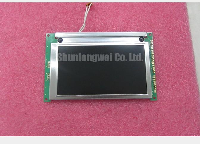
The KOE / Hitachi LMG7412PLFF is identified as an industrial LCD/HMI panel within the FSTN / STN monochrome passive-matrix category. Its integration assessment should focus on optical behavior, mechanical fit, display drive, and the existing illumination assembly. This is a passive-matrix replacement task, not an IPS or MVA viewing-angle upgrade.
Compare image visibility with the installed illumination disabled and ambient light falling across the viewing surface. As a Design Consideration, this separates illumination-dependent visibility from reflected-light behavior without assuming that the LMG7412PLFF has a particular transflective optical construction. Keep the displayed test pattern unchanged while adjusting the observation angle; changing content and angle together can conceal a contrast problem.
Look for localized haze, bubbles, edge lifting, and discoloration through the front window. These observations help distinguish a surface or optical-stack issue from missing electrical drive, but they do not establish the polarizer chemistry or prove ultraviolet degradation. Compare the appearance with an unaffected area and inspect the enclosure window separately before assigning the defect to the panel.
Uneven bezel loading can alter the visible image or produce localized optical distortion. An Engineering Recommendation is to inspect mounting alignment, gasket position, and evidence of contact between the window and display surface. Restore the documented mechanical arrangement rather than adding clamping force to improve contrast. Connector compression is not an optical adjustment, and an unsupported pressure setting should not become a repair specification.
For bright-location evaluation, assess readability through the actual protective window at the intended operator position. Optical bonding is an enclosure-level integration choice, not an established feature of this model, and bonding alone does not establish moisture sealing. The Industrial Display & HMI Solutions reference provides broader integration context; acceptance should depend on the assembled equipment’s optical and environmental requirements.
CCFL Ballast Capacitor Impedance Matching and Tube Operating Current Stabilization
Identify the installed illumination hardware and its driver before investigating ballast components or lamp current. CCFL troubleshooting applies only where the equipment documentation establishes a CCFL assembly; it does not establish the LMG7412PLFF backlight type. Lamp ignition voltage, operating current, and insulation spacing must come from the matched lamp, inverter, and equipment specifications rather than a generic repair value.
Field Alert: Disconnect equipment power and follow the inverter discharge procedure before unplugging display or illumination connectors.
As a Design Consideration, separate the low-voltage enable and supply path from the lamp-output path during diagnosis. A shutdown after startup can involve supply instability, protection behavior, connector deterioration, or lamp loading. Check the inverter input and enable behavior against the equipment schematic before treating the lamp as the cause. High-voltage measurements require suitable probes, access precautions, and the equipment’s service procedure.
In a documented CCFL circuit, ballast capacitance and transformer characteristics affect starting behavior and operating current. Changing a capacitor simply to increase brightness can disturb the intended load. Inspect damaged insulation and contamination around the installed high-voltage assembly, then assess repairs against its specified clearances and operating conditions. Do not infer safe spacing from the display model number.
The display signal path and illumination power path should remain separate on the troubleshooting diagram. When comparing equipment architectures with another display such as LM64K101, compare complete interface and illumination requirements; that part number should not be treated as a backlight driver or an established companion module for the LMG7412PLFF.
Restoring Missing Horizontal Display Rows / Vertical Columns: Checking Cables and Connections
Display a stable pattern that makes missing rows and columns visible, then record whether the defect remains at the same screen coordinates. Fixed lines can involve the external cable, controller signals, panel connections, or driver circuitry; their orientation alone does not identify a failed flex bond.
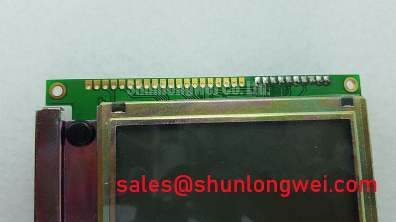
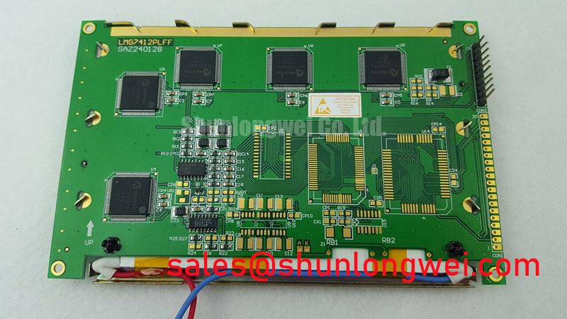
Inspect accessible connectors for incomplete engagement, damaged contacts, cable creasing, and uneven retention. As an Engineering Recommendation, clean only serviceable contacts using the connector manufacturer’s approved method. Do not introduce solvent into bonded panel edges or assume that a visible connection is removable. If the documented construction includes an elastomeric connector, alignment and compression must follow its assembly specification rather than a universal pressure value.
A repeatable change after reseating an external cable supports further investigation of that connection, but does not prove internal delamination. Avoid pressing the glass or heating bonded connections as an exploratory repair. For replacement planning, the comparison below identifies the evidence needed rather than implying interchangeable parts.
| Selection checkpoint | LMG7412PLFF | LM3219T comparison candidate |
|---|---|---|
| Product identity | KOE / Hitachi monochrome passive-matrix LCD/HMI panel | Separate display model requiring its own specification |
| Dimensions and mounting | Consult datasheet and equipment drawing | Compare outline, viewing area, and mounting positions |
| Electrical compatibility | Consult datasheet for supply, connector, and timing requirements | Verify corresponding requirements before connection |
| Replacement status | Original model under evaluation | No drop-in compatibility established here |
The LM3219T can be included in a documented sourcing comparison, not selected solely by appearance. For potential CNC operator-panel or robot teach-pendant replacements, engineers should compare the connector assignment, optical orientation, controller support, and enclosure fit before approving either mechanical or electrical adaptation.
Parallel Digital Signal Reflections Mitigation via Series Damping Termination Resistors
Trace the controller-to-display connection before interpreting clock activity or adding series resistors. Where the equipment schematic identifies FLM frame synchronization, LP line pulses, and CP dot-clock signals, evaluate those signals using their documented functions and limits; these names alone do not establish the LMG7412PLFF pinout.
As a Design Consideration, compare signals at the transmitting and receiving ends with appropriate probing and grounding. Ringing, slow transitions, and inconsistent sampling can involve cable routing, return-path discontinuities, or loading. Series damping is a possible controller-side remedy, but its placement and resistance require validation against the actual driver, interconnect, and receiver timing—not a universal resistor prescription.
The distinction between refresh rate and liquid-crystal response matters when assessing flicker or slow transitions: changing frame timing is not automatically a repair for either symptom. Likewise, Modbus belongs to equipment communications, not the raw display interface. Correct network traffic does not confirm correct panel timing.
Capture supply, bias, signal-enable, and shutdown behavior against the controller and panel sequencing requirements. A white screen or retained image can have several causes, so compare startup and power-down traces with the intended sequence before altering firmware. Maintain the specified alternating liquid-crystal drive and avoid sustained unintended DC bias; acceptance should include stable images during operation and controlled image removal during shutdown.