

Content last revised on October 14, 2026
Logic Supply Voltage Sequencing and Driver Input Verification
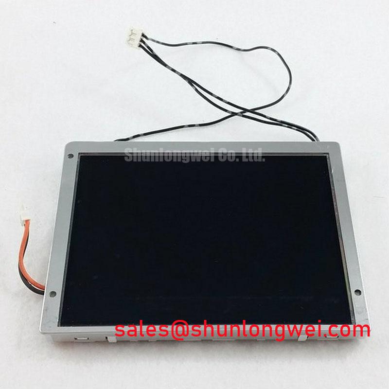
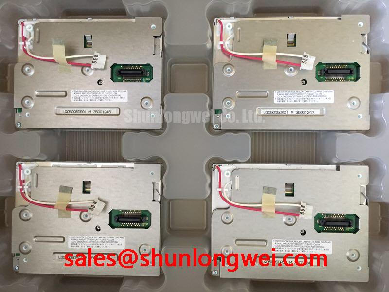
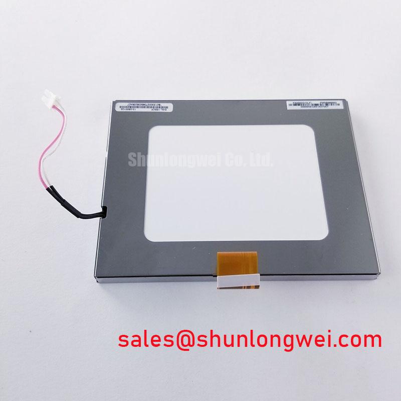
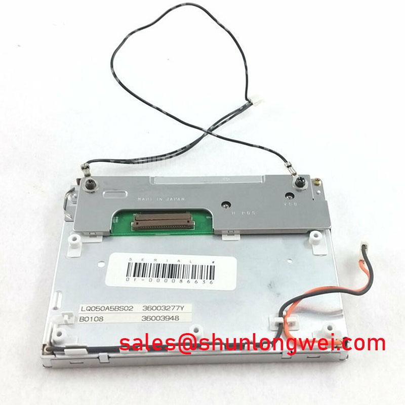
Model: LQ050A5BS02 | Manufacturer: Sharp | Display: 5.0-inch a-Si TFT-LCD | Resolution: 320 × 234 pixels | Mode: Transmissive | Backlight: CCFL | Touchscreen: No | Operating and storage temperature: −30°C to +85°C | Electrical interface and timing: Consult Datasheet
I check the panel supply and incoming signal activity together before attributing a blank or unstable screen to the LQ050A5BS02. As an Engineering Recommendation, capture the supply at the panel connector during startup, shutdown, and an interrupted power cycle. A measurement taken only at the controller board can overlook voltage disturbances across the harness or connector. Compare the captured sequence with the panel requirements and the equipment schematic, including when the controller begins transmitting image data.
The system integrator should verify the required supply voltage from the original panel documentation. Connector position, cable appearance, and screen size do not establish electrical compatibility. Identify the supply, return, signal, and backlight connections before energizing a replacement. Where the controller can drive inputs while panel power is absent, assess the sequencing against the receiving circuit requirements rather than assuming that a working image proves the startup arrangement is acceptable.
Design Consideration: separate supply disturbances from image-format problems during diagnosis. A split image, shifted picture, or missing region can arise from controller timing, connection integrity, or a mismatched signal assignment. Use a stable test image and compare the signal path with a known-good assembly. Apply JEIDA or VESA mapping checks only when the actual interface documentation identifies those conventions; they are not established specifications for this panel.
The product specifications identify a 5.0-inch, 320 × 234-pixel, transmissive a-Si TFT-LCD with a CCFL backlight and no touchscreen. These characteristics define the starting point for replacement assessment. Mechanical outline, mounting locations, connector orientation, electrical pin assignment, and controller compatibility remain separate checks. The linked LQ050A5BS02 product page can accompany the procurement record, but the complete model marking should remain the reference for equipment matching.
For comparative sourcing, the LQ10D41 can be reviewed as another display candidate, not treated as an interchangeable replacement. Compare its actual dimensions, resolution, interface, optical characteristics, and backlight requirements before assessing suitability. A model appearing in the same supplier catalog does not establish equivalence.
💡 Bench Tip: With power isolated and ESD precautions in place, seat the display cable squarely and secure its retention mechanism before restoring power.
For installations without a separate touch assembly, acceptance testing should focus on image presentation and the equipment’s existing controls. Glove operation, wet-touch sensitivity, and touch-controller calibration are not attributes of this non-touch panel. If the equipment incorporates an external touch overlay, evaluate that assembly independently, including its mounting pressure and effect on visibility.
Viewing-Angle Assessment and Full-Screen Optical Inspection
Run full-screen white, black, primary-color, and gray patterns before judging the panel from a normal equipment screen. As an Engineering Recommendation, inspect the entire active area under repeatable ambient illumination and viewing position. A busy interface can conceal isolated pixel defects, faint lines, or uneven illumination. Record the location and appearance of each observation so that a later inspection compares the same region rather than relying on visual memory.
Use white and intermediate-gray patterns to examine brightness and apparent color uniformity, then use a dark pattern to distinguish visible bright points from reflected room light. Keep the display settings and test content unchanged during comparison. Camera images can support the inspection record, but automatic exposure and white balance can exaggerate or hide differences. A controlled optical measurement is more useful than photographs taken under changing conditions.
Design Consideration: check grayscale readability from the actual operator positions. The designation a-Si TFT-LCD does not establish an IPS or MVA structure, a symmetric viewing cone, or a particular viewing-angle limit. Move through the anticipated viewing positions and observe whether dark detail disappears, pale regions merge, or the apparent contrast changes. Evaluate these effects with the enclosure window installed when that window forms part of the equipment.
The color temperature and white-point reference explains the distinction between perceived warm or cool appearance and chromaticity. For incoming inspection, compare the center and edges using the same instrument settings and stabilization conditions. A visibly different white region warrants examination of the illumination path and assembly condition; it does not identify a single failed component or establish an acceptance threshold by itself.
Mechanical fit deserves attention during optical testing. As an Engineering Recommendation, support the panel through the intended mounting features and examine the image after assembly. Uneven frame loading, cable tension, or contact with the enclosure can influence the observed result. If an optical irregularity changes after mounting, compare the installed condition with the supported bench condition before assigning the fault to the display.
When evaluating this panel for a high-voltage substation protection terminal or SCADA dispatch console, designers should assess alarm-text readability, viewing position, enclosure reflections, and compatibility with the existing controller. This is an equipment-level suitability assessment, not a statement that the panel was specifically designed or certified for that application. Its compact size and stated temperature range are relevant inputs, while readability must be demonstrated in the assembled terminal.
Radiated Emissions Assessment and Display Harness Grounding
Correlate pixel disturbance or horizontal noise with equipment activity before changing the display harness or grounding arrangement. As an Engineering Recommendation, hold the displayed pattern constant while observing startup events, switching loads, and backlight operation. Repeatable timing can help distinguish an interference-related symptom from an intermittent connector or controller problem, although correlation alone does not establish the coupling path.
Design Consideration: preserve the intended signal-return paths and inspect the harness routing against the equipment schematic. Where shielding is present, evaluate its termination as part of the complete enclosure and grounding arrangement. Additional grounding points or ferrites can alter common-mode behavior, but their usefulness depends on the actual cable construction, disturbance spectrum, and return path. Neither accessory should be presented as a standard feature of the LQ050A5BS02.
Interface measurements should follow the electrical interface actually fitted. For a documented differential link, assess the pair geometry, termination, and waveform at the receiver under representative operating conditions. For a documented parallel interface, examine clock-to-data timing and the integrity of the associated returns. Do not impose LVDS routing rules on an unidentified interface, or infer the signaling standard from the number of contacts on the cable.
Clock jitter and data timing require comparison with the controller and receiver specifications. An Engineering Recommendation is to capture the waveform during the conditions that reproduce the fault, rather than relying solely on a clean idle measurement. Probe loading and measurement reference selection can affect the result, so preserve the measurement setup when comparing an affected assembly with a known-good one.
The CCFL backlight requires coordination with the equipment’s inverter circuit. Inspect the lamp connections, inverter supply, enable behavior, and any documented fault output. If illumination disappears while image data remains active, separate the backlight investigation from the logic investigation. Open-lamp detection, protection thresholds, and restart behavior belong to the installed inverter design; they are not established panel specifications.
The TCG057QV1AA-G10 is another display product to consider during broader display-and-power architecture comparisons, not a backlight driver for this Sharp panel. Any comparison should keep the display module, its required illumination supply, and the controller interface distinct. Matching one subsystem does not demonstrate compatibility of the complete assembly.
CISPR emissions classification applies to the evaluated equipment configuration, not automatically to a replacement display module. As a Design Consideration, retain the enclosure, cable routing, shielding, and grounding conditions used for the equipment’s compliance assessment. If integration changes those conditions, the responsible system team should determine the necessary verification. A visually stable picture is not evidence of emissions compliance.
Cold-Start Response and Temperature-Dependent Backlight Checks
Compare image transitions and illumination from a cold start with the same test after thermal stabilization. The stated operating temperature is −30°C to +85°C, and the stated storage temperature is −30°C to +85°C. These limits do not specify a constant gray-to-gray response time, contrast ratio, or startup brightness throughout that range. Keep the test pattern, drive conditions, and observation method consistent so that temperature-dependent behavior can be distinguished from setup changes.
Design Consideration: liquid-crystal switching behavior changes with temperature, and colder operation can slow visible transitions. The general liquid-crystal reference provides background on temperature-sensitive liquid-crystal phases and behavior; it does not establish a response-time rating for this model. Inspect transitions between intermediate gray levels as well as black and white, because moving text and changing symbols can reveal effects that a static image does not.
Evaluate the CCFL illumination separately during cold-start testing. Record whether brightness develops uniformly, whether the apparent white point changes during warm-up, and whether the inverter reports a fault. Compare observations with the equipment’s startup requirements. A slow image transition and delayed illumination can coexist without sharing the same cause, so maintain separate records for image response and backlight behavior.
If the host equipment uses thermal control, assess its effect on the installed panel temperature and visible performance. A heater is an equipment-level option, not an identified feature of the LQ050A5BS02. Avoid direct thermal loading or modifications to the panel assembly without an approved integration method. Inspect for enclosure contact, cable restraint, and moisture conditions when moving between test environments.
The Ultimate Guide to Industrial TFT LCD Technology offers supplementary integration background, rather than a model-specific acceptance standard. For this panel, retain actual temperature, transition, and illumination observations in the equipment validation record. Do not infer sealant composition, thermal-cycle endurance, or service life from the operating-temperature range.
For bright-ambient testing, place representative text and symbols behind the intended enclosure window and assess readability under the installation’s lighting conditions. As an Engineering Recommendation, compare reflected light, viewing position, and backlight output together. Anti-glare or anti-reflection treatment and sunlight contrast are not established specifications here; acceptance should rest on measured or observed performance of the complete display assembly under the required conditions.