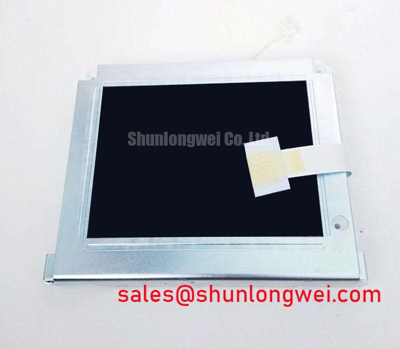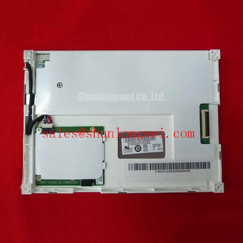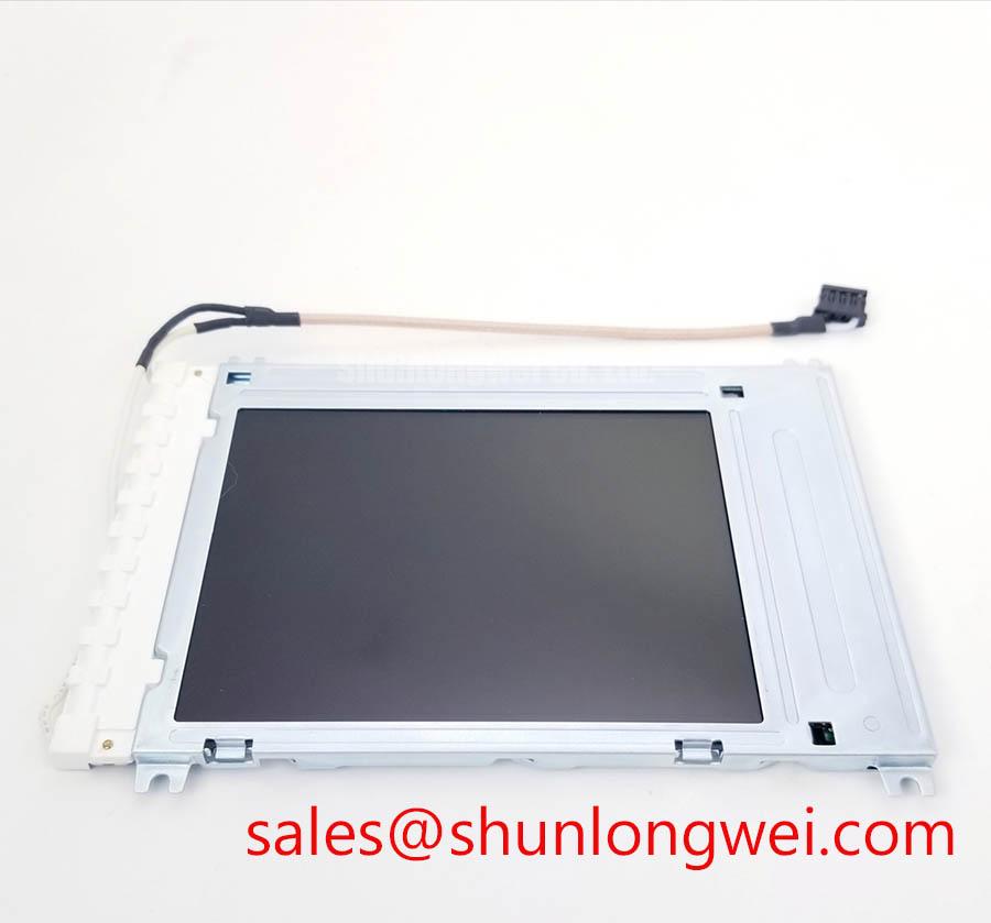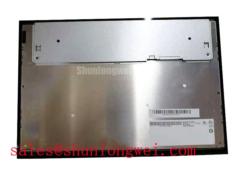


Content last revised on October 16, 2026
High-Humidity Storage Margins (60°C / 90% RH) & Delamination Prevention Protocols
Inspect the display perimeter for lifting, persistent haze, and evidence of moisture before energizing a panel transferred from cold storage. Design Consideration: the temperature and humidity condition in this heading is an environmental assessment topic, not an established LQ12S56 storage rating. Storage acceptance depends on the manufacturer's environmental limits, packaging requirements, and permitted exposure duration.
Allow a cold assembly to reach equilibrium with the service environment before opening its protective packaging. Condensation can affect exposed connections and obscure the distinction between surface moisture and damage within an optical assembly. Examine suspected separation under changing illumination angles, checking whether the feature remains fixed when the displayed image changes. Avoid pressing the viewing surface to test whether a cloudy area disappears.
At low temperature, liquid crystal response can slow, producing trailing transitions even when the controller continues to send valid image data. Compare the same moving pattern after the assembly stabilizes at different permitted operating temperatures. This helps distinguish temperature dependent response from a persistent signal or illumination fault without inventing a gray-to-gray response specification.
If the host equipment includes a heater, assess its sensing location, control behavior, and temperature distribution as part of that equipment's design. A heater is not an established LQ12S56 accessory. Where an external cover or optical bonding assembly is present, inspect its edges separately: bonding can affect reflections and moisture pathways, but does not establish a hermetic enclosure. Manufacturer resources such as Sharp Devices Europe Industrial Display Solutions provide context for industrial display selection.
VESA vs. JEIDA Data Mapping Alignment & Even/Odd Channel Signal Integrity
Trace the host controller connector to the panel connector before changing data mapping settings or substituting a cable. Design Consideration: VESA and JEIDA mapping checks apply when the documented interface uses the corresponding LVDS conventions; this heading does not establish an LVDS interface or channel arrangement for the LQ12S56. Connector fit alone cannot establish electrical compatibility.
For an applicable interface, compare the transmitter configuration, receiver assignments, color bit positions, and channel ordering. Incorrect mapping can alter grayscale progression or color reproduction. Split images and displaced patterns also warrant checking timing, channel assignment, and cable continuity rather than treating the visible symptom as proof of one fault.
Capture the panel supply, controller enable, and illumination control signals during startup and shutdown against the equipment timing requirements. Measure at the receiving connector where practical, because cable and contact losses can change the waveform reaching the assembly. A white screen or retained image after shutdown calls for checking supply decay and signal sequencing alongside the image path.
Field Alert: Disconnect equipment power and allow stored energy to discharge before inserting or removing display connectors. If incorrect grayscale remains after configuration and cable checks, follow the documented timing controller test points for supply and reference voltage assessment; avoid adjusting gamma circuitry to compensate for an unresolved mapping error. The Sharp LQ181E1LW31 can be included in a separate compatibility comparison, but direct replacement requires matching electrical, optical, and mechanical specifications. For a CNC operator panel or robot teach pendant, include the host controller and mounting arrangement in that comparison.
Surface Anti-Glare (AG) & Anti-Reflective (AR) Etched Coating for High Ambient Readability
Compare readability with the enclosure closed and the normal surrounding lights operating, then change the observer's position while displaying a grayscale pattern. Design Consideration: this check distinguishes reflected glare, viewing direction effects, and illumination unevenness without assigning an unverified coating or liquid crystal mode to the LQ12S56.
Anti-glare treatments scatter reflections, while anti-reflective treatments reduce reflected light through a different optical approach. Neither term establishes the surface construction of this model. Evaluate the complete viewing stack, including any protective window or touch assembly, because its surfaces can dominate the reflection seen by the operator. Use cleaning materials approved for the actual exposed surface.
Viewing angle changes can shift apparent contrast and grayscale ordering. Compare the installed viewing position with a straight-on reference before attributing poor visibility to controller gamma settings. TN, IPS, and MVA describe different liquid crystal approaches; their general behavior cannot establish this panel's technology or a symmetric viewing angle specification. A dark-room contrast ratio also does not establish readability under strong ambient illumination.
For localized dimming or color variation, display uniform fields and compare the pattern after thermal stabilization. Check whether enclosure pressure, nearby heat sources, or illumination distribution changes the result. Inspect backlight supply behavior before assigning the fault to an optical layer. The Sharp Display Solutions Official Portal offers broader display context; model acceptance should remain tied to its specified optical conditions and the installed viewing geometry.
Shielded FFC/FPC Flat Flexible Cable Grounding across 360-Degree Connector Shells
Inspect cable retention, exposed contacts, bend locations, and the documented chassis connection before adding suppression components. Design Consideration: the cable construction, shielding arrangement, and connector shell described in this heading are integration topics, not established LQ12S56 hardware features. Apply shield termination methods only to a cable assembly designed to support them.
When image disturbance changes with nearby switching equipment, compare operation under controlled load conditions and examine both the receiving supply and signal path. Horizontal bands or pixel instability can have several contributors, including supply disturbance, contact problems, and coupled interference. A repeatable relationship with machine operation narrows the investigation but does not identify the coupling path by itself.
Preserve the intended signal return path and inspect shield connections against the equipment grounding plan. Route display wiring away from power switching conductors where the enclosure permits, then verify the result under representative operating conditions. Broad shield contact can support high frequency continuity when compatible connector hardware provides it; avoid improvising connections to signal ground.
Use the system checks discussed in Industrial Display & HMI Solutions to organize cable, enclosure, and supply investigations. If a ferrite or revised shield termination is evaluated, compare image stability and signal quality before and after the change. Confirm satisfactory startup, normal operation, and shutdown with the final cable routing and enclosure fully assembled.