



Content last revised on September 10, 2026
Aluminum Heat Spreader Sizing & Thermal Interface Placement along Narrow Display Edges
For an industrial operator station, begin the thermal review at the display perimeter rather than assuming that the metal bezel provides uniform heat distribution. Narrow edge regions can experience different thermal conditions from the central viewing area when the backlight, driver electronics, or enclosure ventilation is asymmetrical. A replacement assessment should therefore document the position of the original heat-spreading parts, insulating films, mounting brackets, and any contact surfaces that transfer heat into the chassis.
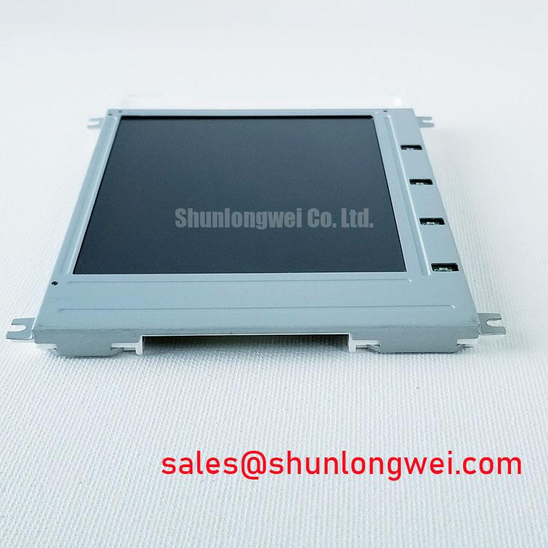
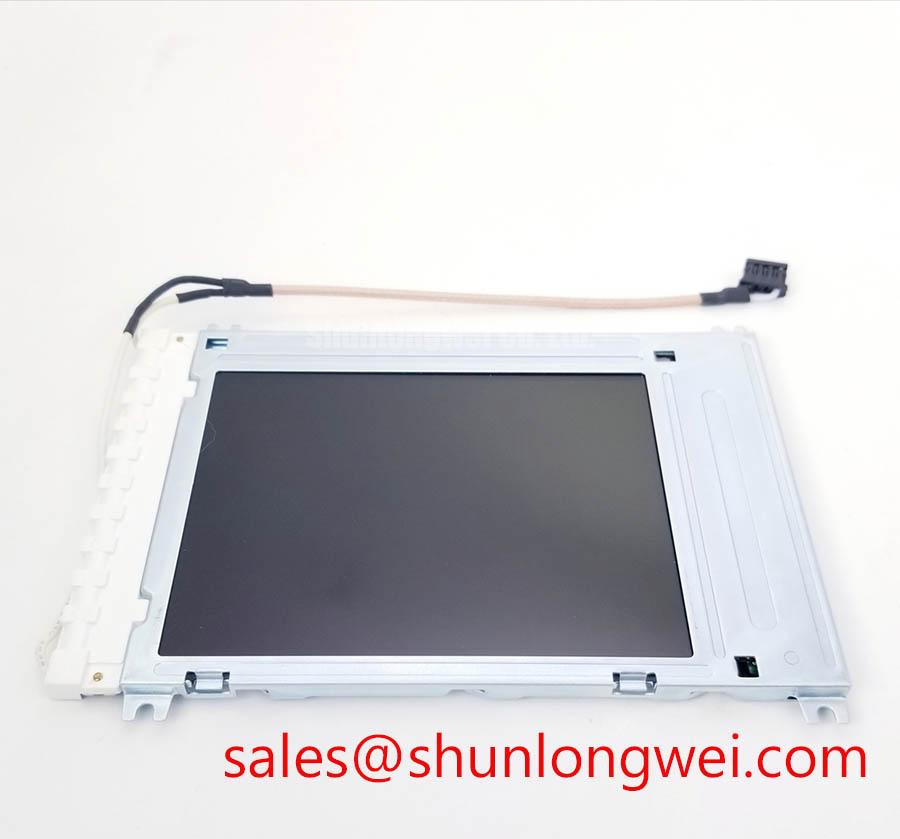
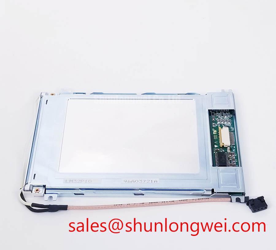
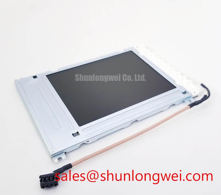
The LM32P10 is identified in the supplied product data as a Sharp TFT LCD display module, but the available factory parameters do not confirm a specific LED configuration, backlight current, backlight lifetime rating, or thermal resistance. These values must not be inferred from the model number. The system integrator should verify the backlight technology, driver topology, current regulation method, enable signal, dimming method, and protection behavior from the original panel documentation and the installed control board.
Where the host uses a constant-current backlight driver, the engineering review should focus on current stability, heat produced along the display edges, and the thermal path from the driver assembly to the enclosure. A heat spreader rail can be evaluated as a system-level design measure when localized heating is observed, but its thickness, length, attachment method, and electrical isolation remain dependent on the enclosure and panel construction. The rail should not press against the active display area, flexible cable, optical stack, or connector housing.
Statements about a 50,000-hour backlight life, L70 or B50 performance, or LED MTBF should be used only when supported by the relevant Sharp specification or an applicable test report. Those figures are influenced by junction temperature, drive current, duty cycle, ambient temperature, and airflow. They are not established by the supplied LM32P10 information. During service testing, compare brightness uniformity at cold start and after thermal stabilization, while checking for localized heating and changes in the backlight current waveform.
In a Zone 2 explosion-proof petrochemical operator station, the display is only one element inside a certified equipment assembly. The panel itself should not be described as independently certified for hazardous-area use, EMC compliance, or enclosure protection. Designers should verify the complete station’s certification method, enclosure construction, cable glands, bonding, temperature classification, and service procedure. The broader Industrial Display & HMI Solutions reference can support a wider review of display integration conditions.
TTL 24-Bit Digital RGB Bus Synchronization & Logic Power Rail Verification
Before connecting the display to a controller, identify whether the installed system actually uses a TTL RGB interface, LVDS, or another display bus. The supplied factory context does not confirm the LM32P10 signal standard, pixel format, bit depth, logic voltage, pin assignment, or power-on timing. The system integrator should verify these items from the original Sharp panel documentation rather than selecting a 3.3 V or 5.0 V rail by assumption.
For a TTL 24-bit RGB implementation, the practical inspection should cover pixel clock polarity, horizontal and vertical synchronization, data-enable behavior, and the ordering of the red, green, and blue bit groups. JEIDA and VESA mapping terminology is more commonly associated with serialized LVDS links, so it should not be applied to this model unless the actual interface board confirms an LVDS conversion stage. A mismatch in mapping or clock interpretation may appear as incorrect colors, unstable text, split-screen imagery, or an image that shifts during signal transitions. Confirm the signal path with a known-good controller or oscilloscope comparison instead of assigning a single cause from the visual symptom.
Power sequencing also requires documentation-based verification. Check the logic rail at the panel connector, observe its rise and discharge behavior, and confirm that display enable and video activity follow the sequence required by the host electronics. The supplied information does not establish a permitted rise-time window for LM32P10. Any timing limits used in the repair should come from the original panel specification or the system manufacturer’s service documentation.
Signal integrity is a board-level responsibility. Keep high-speed signal paths short, maintain a continuous reference plane where the PCB permits, and avoid routing display data beside noisy backlight switching nodes. For differential links, the designer should control the characteristic impedance and length relationship according to the transceiver and cable specification. For single-ended TTL RGB, the relevant checks are edge rate, return-current path, ground reference, overshoot, and input threshold compatibility. These are design considerations, not confirmed LM32P10 factory ratings.
The cable and connector deserve the same attention as the controller. Inspect the flexible cable for creases, lifted contacts, contamination, and incomplete insertion. Confirm that the locking actuator is fully seated and that the cable exits without a sharp mechanical load. Intermittent video faults can be affected by connector retention, ground continuity, timing configuration, or controller behavior, so service diagnostics should isolate each section of the path.
When the original assembly uses a related display architecture, engineers may review the LM64P10 as a separate Sharp display reference, but no pinout, electrical compatibility, or direct substitution relationship should be assumed without comparing the two original datasheets.
💡 Pro Tip: Keep the display clock and associated data conductors arranged with consistent reference conditions through the connector transition, then verify the received image under both static test patterns and real operating content.
Industrial Bezel Mechanical Envelope Tolerances & Mounting Screw Torque Optimization
Mechanical compatibility should be checked before any electrical substitution. Measure the available bezel opening, panel support points, connector clearance, cable exit direction, rear-component keep-out area, and compression points in the host chassis. The available LM32P10 factory context confirms a TFT LCD Display Module but does not provide outer dimensions, active-area size, mounting-hole coordinates, panel thickness, or fastener specification. These physical values must be taken from the original drawing or measured from the installed part.
Do not use the bezel to force a panel into alignment. A display that fits the opening but is restrained unevenly can experience frame stress, optical non-uniformity, connector loading, or image changes when the enclosure is tightened. The replacement should sit against its intended supports without bending the glass assembly or trapping the FPC. If a gasket, spacer, or insulating sheet is present in the original construction, record its position and thickness before removal, then confirm that it does not obstruct ventilation or create a conductive path.
Cross-pattern tightening is a useful general installation practice for distributing mechanical load, but the correct fastener type and torque are determined by the chassis design and the panel manufacturer’s mechanical specification. The supplied data does not confirm an M3 fastener or a 0.35 to 0.45 N·m limit for LM32P10. Those values must not be presented as official ratings for this model. Instead, use the documented assembly torque where available and validate the result by checking bezel flatness, image uniformity, and connector retention after installation.
Backlight control should be traced from the panel connector to the host driver. The available information does not confirm whether LM32P10 requires PWM dimming, analog current control, a dedicated enable line, or a particular backlight supply. If PWM is used by the installed system, the controller designer may evaluate a frequency range suitable for the camera environment, optical response, audible behavior, and control-loop design. A nominal 200 Hz to 1 kHz range belongs to system evaluation unless it is explicitly stated in the original panel documentation.
For a hazardous-area control station, the bezel interface also affects sealing and serviceability. Check that the display window, gasket compression, cable routing, and fastener access remain consistent with the certified enclosure design. The panel should not be treated as the component that establishes Zone 2 compliance. Any modification to the viewing window, mounting frame, grounding arrangement, or cable entry requires review by the responsible equipment designer.
For a same-class sourcing comparison, the LM190E08-TLG6 may be examined as a separate display product. Compare its dimensions, interface, optical characteristics, mounting method, and backlight requirements independently; model-family naming alone does not establish interchangeability.
Dynamic Contrast Ratio Stabilization & Liquid Crystal Birefringence Temperature Tracking
Image quality testing should begin with a controlled visual pattern and the original controller settings. Record black level, white level, grayscale transitions, viewing direction, backlight setting, and ambient illumination before comparing a replacement. The supplied LM32P10 parameters do not confirm a contrast ratio, panel technology such as TN, IPS, or MVA, viewing-angle specification, anti-glare treatment, or response-time rating. Those characteristics should be verified from the original Sharp documentation rather than assigned from the product category.
Temperature can change liquid-crystal response and alter the appearance of grayscale transitions. In a cold equipment room or outdoor monitoring cabinet, allow the display assembly and controller to reach the intended operating condition before judging response time or contrast stability. A heater strip may be considered at system level when the enclosure requires controlled warm-up, but its placement, control logic, safety behavior, and temperature limits must be determined from the complete equipment design. No specific cold-start range or compensation profile is confirmed for LM32P10 in the supplied factory data.
At high ambient illumination, the practical question is whether the operator can distinguish status text, alarms, and process values through the installed window and surface treatment. Evaluate the complete optical stack, including enclosure glass, protective film, viewing angle, reflections, and display brightness. A contrast value above 500:1 at 50,000 lux cannot be attributed to this model without a supporting factory specification or test report. The same applies to claims about an anti-glare coating or etched surface.
Backlight faults should be diagnosed at the system interface. Check the driver output, enable state, current regulation, connector continuity, and fault feedback where provided by the host board. An open or short indication may originate in the backlight assembly, cable, driver, protection circuit, or controller configuration. Compare the measured behavior with a known-good panel and the documented electrical limits; do not infer a definitive failure from one voltage reading.
Vibration and thermal expansion review should include the panel frame, bezel, connector latch, flexible cable bend path, and enclosure supports. Designers should provide stress relief and allow the mechanical assembly to accommodate normal expansion without transferring force into the glass or FPC. The appropriate solution depends on the original mechanical drawing and the certified equipment enclosure. For procurement and repair records, retain the verified model marking, panel documentation, interface drawing, and post-installation functional test results with the equipment service file.