

Content last revised on September 10, 2026
LQ104S1LG21 Identification and Compatibility Checks
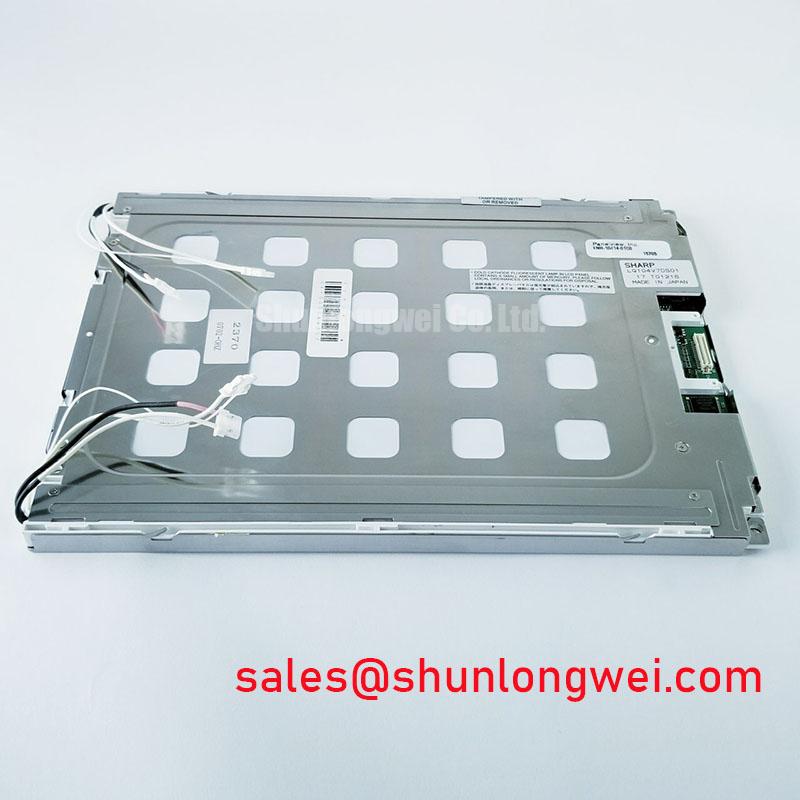
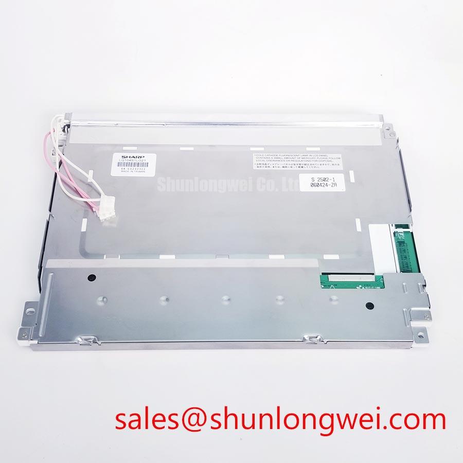
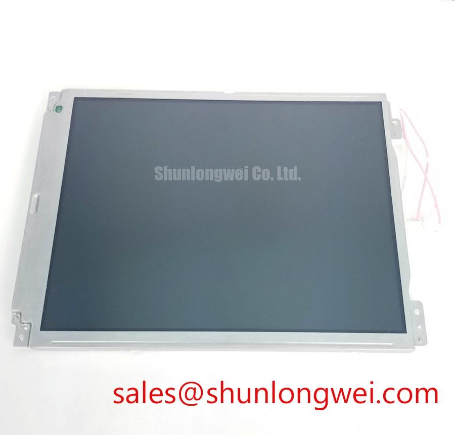
Begin the bench inspection by confirming the Sharp nameplate and measuring the panel harness for unintended shorts with power removed, then compare the connector position, mounting points, and visible glass area with the original unit before applying power. The LQ104S1LG21 is identified here as a Sharp TFT LCD Display Module for industrial display and HMI integration. The available factory information confirms its manufacturer, module category, and official specification status, but does not confirm a resolution, interface type, supply voltage, backlight technology, optical coating, touch function, or mechanical drawing. Those values must be taken from the original panel documentation and the equipment service file rather than inferred from the model number.
| Item | Verified information |
|---|---|
| Model | LQ104S1LG21 |
| Manufacturer | Sharp |
| Product category | Industrial Grade LCD/HMI Panel |
| Module form | TFT LCD Display Module |
| Specification status | Official Factory Spec Verified |
| Primary engineering task | Verify electrical, optical, mechanical, and backlight compatibility from the original documentation |
For procurement and field replacement, the model identifier should be matched character by character, including the suffix. A visually similar TFT panel can still use a different pixel format, connector assignment, timing convention, backlight circuit, or mounting geometry. Designers should record the removed panel’s connector orientation, cable length, bezel opening, fixing method, and controller settings before disassembly. The system integrator should verify the required supply voltage from the original panel documentation. The same verification applies to the video input, enable sequence, brightness control, and touch interface if the host equipment includes touch operation.
Full Screen Primary Color AOI Screening and Background Uniformity Audit
After a safe initial power test, display full screen red, green, blue, black, white, and mid gray patterns through the existing controller. This inspection is useful for separating visible pixel defects from problems in the signal path or backlight assembly. A stuck sub pixel normally remains visible when the displayed color changes, while a broad luminance variation may follow the illumination system, diffuser path, cable connection, or controller output. The result should be documented with the same image pattern, viewing angle, ambient lighting, and camera exposure used for the comparison panel.
A dark room check can be followed by a 45 degree flashlight inspection with the display unpowered. Moving the light across the front surface may reveal scratches, pressure marks, contamination, edge damage, or an optical irregularity that is difficult to see under normal operation. This method does not prove a specific internal failure mode. A line defect that follows a glass edge, bonding region, or fixed row and column position should be compared with the known good signal path and the panel cable seating. If the defect changes after cable movement, inspect connector retention and mechanical strain without flexing the glass.
The factory data supplied for this product does not establish a specified gray to gray response time or a validated operating range for sub zero conditions. Cold testing should therefore be treated as a Design Consideration, not as a confirmed LQ104S1LG21 performance rating. At low ambient temperature, liquid crystal response can become slower and gray transitions may show visible trailing. If the equipment includes a heater strip or enclosure temperature control, the control sequence should be checked against the panel documentation. The display should reach the permitted operating condition before image quality is judged, and the engineer should monitor the panel supply, backlight enable, and image timing together.
For a replacement review, an apparently clean image is not sufficient. Check whether the controller is generating the expected clock and data activity, whether the panel enable signal follows the host sequence, and whether the image remains stable during connector and enclosure movement. Any oscilloscope work should use the equipment’s approved probing method to avoid loading a high speed display signal. A compatible alternative may be evaluated through the LMS700KF01-001 product page, but its electrical and mechanical compatibility must be confirmed independently before substitution.
Diffuser Film and Prism Sheet Thermal Buckling Prevention During Continuous Operation
Inspect the active area and edge illumination after the display has operated long enough to reach a representative thermal condition. Look for expanding bright spots, edge shadows, localized color changes, or patterns that appear only after warm up. These observations can point to a thermal or optical assembly issue, but they should not be assigned to a particular diffuser, prism sheet, or material without the applicable construction drawing. The available factory context for the LQ104S1LG21 does not specify its optical film materials, LED rating, CCFL arrangement, or permitted temperature limits.
A Design Consideration for enclosure integration is to spread heat through the surrounding structure while avoiding direct pressure on the glass, polarizer, or optical stack. A narrow metal rail can be assessed along the display edge when it improves enclosure heat distribution, provided it does not obstruct the backlight path, interfere with the frame, or transfer concentrated stress into the module. The final rail shape, contact method, and thermal interface remain system decisions that require inspection of the original mechanical assembly.
Continuous full duty operation should be evaluated with the real controller, brightness command, enclosure, and airflow condition. Record the luminance appearance at startup and after the equipment reaches its normal thermal state. If brightness changes with temperature, compare the backlight drive behavior with the host circuit and check for current regulation instability, connector resistance, or protection cycling. The product information supplied here does not provide a certified L70, B50, MTBF, or half life value, so no service life figure should be assigned to this model from general display industry assumptions.
Backlight fault investigation should start at the system boundary. Verify the driver input, enable command, current feedback, open load response, and short circuit response according to the original driver documentation. A dark screen may involve the panel, the controller, the cable, the backlight driver, or a protection state. An overvoltage event should be investigated by examining the driver waveform and load condition rather than by replacing the panel repeatedly. If a related display solution is being reviewed, the LQ9D03B page can be considered as a separate complementary product reference; it is not evidence that the two products share an electrical pinout or backlight architecture.
Surface Anti Glare and Anti Reflective Treatment for High Ambient Readability
For a bridge console, outdoor monitoring panel, or other high ambient installation, evaluate the complete optical path rather than the LCD glass alone. Place the display in the intended bezel and inspect reflections from windows, overhead lighting, navigation equipment, and protective covers. A matte surface can reduce mirror like reflections, while an anti reflective treatment can reduce the intensity of reflected light through a different optical mechanism. The supplied factory data does not confirm whether the LQ104S1LG21 includes an AG surface, an AR layer, a bonded cover, or a defined contrast ratio under sunlight.
Use controlled test images with black, white, and mid gray fields, then compare readability from the actual operator position. Pay attention to black level lift, gray scale compression, color shift, and viewing angle changes caused by the bezel or cover glass. Do not assign the panel to a TN, IPS, or MVA category without an authoritative panel data sheet. Likewise, viewing angle values must not be copied from another display simply because the diagonal class appears similar. The practical result depends on panel construction, cover reflections, controller settings, observer position, and ambient illumination.
Signal integrity is another part of optical stability because intermittent data errors can appear as flicker, sparkles, vertical noise, or an unstable image. If the interface is LVDS, the system engineer should verify the actual pair assignment, polarity, clock relationship, and data mapping from the original documentation. JEIDA and VESA formats are not interchangeable assumptions. If the host uses TTL or another interface, the same rule applies: confirm the electrical standard and timing before connecting the module.
As a Design Consideration, route high speed differential signals as a controlled, continuous pair with a clean return path and matched propagation behavior; the system designer must determine the target impedance and allowable skew from the controller, cable, connector, and panel documentation. In a factory containing servo drives or switching equipment, verify the signal at the panel connector with the enclosure closed and the machine operating. Compare the suspect unit with a known good path, and inspect cable shielding termination and ground continuity before changing controller timing. This approach avoids treating a display artifact as proof of a panel defect.
Backlight Drive, Dimming Control, and Flicker Fault Diagnosis
Do not assume that the LQ104S1LG21 uses WLED, CCFL, or a particular dimming method from the model number alone. The available official hardware context identifies a TFT LCD Display Module but does not publish a backlight type, ignition requirement, LED current, PWM ratio, optical lifetime, or dimming frequency. The original service documentation must establish these values. If a replacement harness or driver is being considered, match the connector, polarity, enable logic, brightness control, and protection behavior before energizing the module.
For a suspected backlight open circuit, first confirm that the host is requesting illumination and that the driver has its required input conditions. Then inspect the output waveform using an instrument and probe arrangement suitable for the driver. An open load can trigger protection, but a dark display can also result from missing enable logic, a failed controller, cable damage, or a supply fault. For a suspected short condition, look for protection cycling, abnormal current feedback, connector heating, and changes in brightness during controlled testing. These observations narrow the fault domain without claiming a single cause.
When PWM dimming is present, observe the brightness command and the light output together. Flicker can be related to control frequency, duty command, driver regulation, camera interaction, grounding, or a signal integrity problem. The correct adjustment is system determined and should be validated with the actual enclosure, controller, and user brightness range. No verified factory information supplied for this page supports a claim of 1000:1 PWM dimming, acoustic noise performance, or a guaranteed service life for the LQ104S1LG21.
Touch operation requires the same discipline. The product information provided does not confirm a resistive or capacitive touch layer, glove sensitivity, water tolerance, or touch controller interface. If the host assembly includes touch, verify the touch overlay model, controller connection, calibration file, and sealing arrangement separately. A failed touch response may involve the overlay, controller, cable, firmware, or environmental contamination, so test each interface with the original equipment configuration.
Bench Diagnostic: Disconnect power before inserting or removing the panel cable, then confirm connector keying and pin orientation before the next test.
For enclosure-level troubleshooting and preventive integration practices, engineers can consult Industrial Display and HMI Solutions. The LQ104S1LG21 remains suitable for evaluation when its verified identity is matched with the host system’s electrical, optical, thermal, mechanical, and environmental requirements.