




Content last revised on September 30, 2026
Display Optical Stack and Thermal Buckling Checks under Continuous Operation
| Model | LQ121S1DG41 |
| Manufacturer | Sharp |
| Product Category | TFT LCD module |
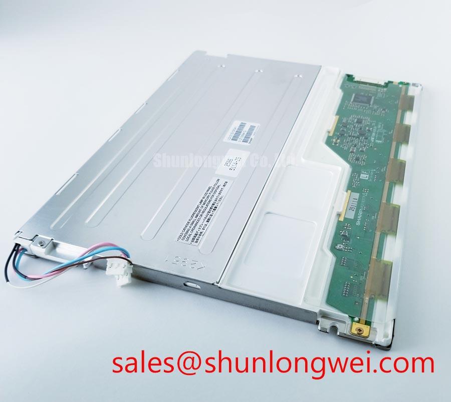
| Package and Construction | TFT LCD Active Matrix Color Display Module |
Illuminate the complete display surface with a uniform test pattern and inspect the panel at several viewing angles before connecting it to the equipment enclosure. This check helps reveal localized brightness variation, optical contamination, edge shadowing, or pressure related mura that may be hidden by normal operating graphics.
The Sharp LQ121S1DG41 is identified as a TFT LCD Active Matrix Color Display Module. The supplied information does not confirm the internal diffuser film, prism sheet, light guide material, LED arrangement, anti glare treatment, anti reflection coating, luminance value, contrast ratio, or backlight lifetime. Those characteristics should not be treated as factory specifications for this model without the original Sharp panel documentation.
For a high brightness marine radar or navigation bridge console, the optical stack should be evaluated as a complete assembly. Designers should inspect whether the bezel, gasket, front window, and panel frame apply uneven pressure during thermal expansion. A narrow heat spreader rail can be considered where the enclosure creates a localized hot zone near the display edge, but its dimensions, material, attachment method, and thermal performance must be established by the system designer through temperature mapping.
Continuous full duty operation also requires a controlled review of the backlight circuit. Confirm the driver topology, current regulation behavior, startup sequence, open load response, short circuit response, and overvoltage protection from the original equipment schematic. The LQ121S1DG41 information supplied here does not establish a specific LED backlight current, input voltage, connector pinout, protection threshold, or rated operating life.
Brightness measurements should be made after the display reaches a stable operating condition, with the same optical window and enclosure geometry used in service. Direct sunlight testing is useful for evaluating glare and readable contrast, but a target such as a specific contrast ratio at a defined illumination level is a system validation criterion rather than an official specification of this panel. Sharp’s industrial display and optics resources provide useful reference context for evaluating display integration requirements.
During incoming inspection, record the full screen response using white, black, red, green, blue, and gray test fields. Look for stuck pixels, intermittent columns, corner shading, color nonuniformity, and changes that appear when the frame is lightly supported. Do not flex the glass or apply pressure to the active area. A change in the image during cable movement should be investigated at the connector, cable retention, and host interface rather than assigned to a single internal cause.
Industrial Bezel Mechanical Envelope Tolerances and Mounting Screw Torque Optimization
Measure the installed bezel opening against the replacement panel frame at several points, then compare the readings with the original mechanical drawing before tightening any fasteners. This immediately separates an incompatible enclosure from a panel that is electrically suitable but mechanically constrained.
The information available for LQ121S1DG41 identifies it as a TFT LCD module, but it does not provide outer dimensions, active area dimensions, mounting hole locations, screw size, frame thickness, or an approved fastening torque. The enclosure designer should therefore use the original Sharp mechanical drawing or the removed panel as the dimensional reference.
Fasteners should be tightened evenly in a cross pattern only after the panel is seated without frame distortion. A general mounting practice is to avoid using screw force to pull a misaligned bezel into position. Excessive or uneven clamping can create visible optical nonuniformity, edge pressure, or intermittent electrical contact. Any torque figure used in production must come from the panel drawing, fastener specification, bracket design, and validation testing rather than being assumed from another LCD family.
Field Alert: Disconnect power before inserting or removing the display cable, and keep the cable fully aligned with the connector before applying the locking mechanism.
Signal integrity must also be treated as an interface compatibility question. The supplied product data does not confirm whether this model uses LVDS, RGB, a serial display interface, or another host connection, and it does not establish pin assignments, differential impedance, voltage levels, timing, or cable length. Do not connect the panel solely because the connector appears mechanically similar.
If the original documentation identifies a differential interface, the system engineer should verify the specified pair routing, termination, return path, and skew against the host design. A commonly used differential impedance value may be relevant to the system interface, but it is not an official LQ121S1DG41 parameter unless stated by the applicable documentation. In a high EMI factory environment, compare the suspect signal with a known good display using suitable probing methods and inspect for edge distortion, common mode movement, and intermittent frame errors.
The linked LQ104V1LG81 can be reviewed as a separate display option during a cross model study, but its dimensions, interface, optical characteristics, and mounting arrangement must be checked independently. Similar display terminology does not establish drop in compatibility.
Mitigating Gray to Gray Response Escalation during Cold Start Machine Power Up
Capture the first several seconds of the display after a cold start while showing a moving gray scale pattern, and record whether image transitions, frame refresh, or backlight behavior changes as the enclosure temperature rises. This test gives the service engineer a useful time reference for separating panel behavior from host processor and timing controller behavior.
Liquid crystal response is temperature dependent, but the official information supplied for this model does not specify gray to gray response time, operating temperature range, storage temperature range, heater requirements, or optical performance during cold start. Any statement about operation at a particular sub zero temperature must therefore be verified against the original Sharp specification and the complete equipment qualification plan.
When a navigation console or outdoor HMI requires cold start operation, the system designer should evaluate the panel, front window, enclosure heater, power supply, and control firmware together. A heater strip may be considered where the approved equipment design requires it, but its location, control logic, thermal limit, and startup timing are system decisions. The display should not be exposed to a rapid temperature transition that produces condensation on electrical or optical surfaces.
Use a calibrated temperature sensor near the panel frame and another at the enclosure air inlet when characterizing startup behavior. Compare image response with the host timing signals and backlight enable state. A slow transition may involve panel temperature, drive timing, supply sequencing, cable integrity, or image processing. Confirm each condition with measurement rather than treating a visible delay as proof of a single failed component.
Perimeter sealants, gaskets, and front window adhesives are enclosure materials and are not confirmed features of the LQ121S1DG41 module specification provided here. Their compatibility with thermal cycling, salt exposure, cleaning agents, and pressure must be qualified by the equipment manufacturer. For a harsh marine installation, enclosure sealing and corrosion control remain separate system responsibilities.
Backlight diagnostics should begin at the driver output and enable control. Check whether the driver reports open load or short circuit protection, whether the current remains regulated during startup, and whether the host removes the enable signal after a fault. The panel listing does not provide a specific protection circuit or fault code scheme, so service procedures should follow the original equipment wiring and driver documentation.
Industrial EMI Noise Immunity, Chassis Shielding Continuity and Common Mode Ferrite Chokes
Inspect the complete display cable path with power removed, checking connector seating, shield termination, chassis bonding, cable routing, and separation from motor drive conductors before analyzing pixel jitter or horizontal noise bands.
The LQ121S1DG41 product data supplied here does not confirm a cable type, LVDS pinout, shield construction, EMC rating, or independent compliance certification. The display module must not be described as independently certified for a complete machine EMC standard. System level immunity depends on the panel, cable, enclosure, power conversion, grounding arrangement, and switching environment.
For an installation near variable frequency drives, maintain a deliberate signal return path and avoid routing the display cable alongside high energy switching conductors where the enclosure design permits. A shield termination method should be selected according to the chassis architecture and verified under the actual operating load. A common mode ferrite may be evaluated when conducted or radiated interference is observed, but its impedance behavior, placement, saturation characteristics, and effect on signal quality must be tested rather than assumed.
Use an oscilloscope or suitable differential probe to compare the signal at the host connector and panel connector. Check whether the disturbance is synchronized with motor switching, backlight current transitions, relay operation, or display refresh activity. If the panel uses a differential interface, verify the complete pair arrangement from the original documentation before applying any termination or filtering change.
Backlight reliability should be discussed using documented manufacturer data. A claim such as a specific operating hour value to a defined brightness percentage is not established by the factory information supplied for LQ121S1DG41. The maintenance engineer should obtain the applicable backlight specification and then evaluate driver temperature, current regulation, ventilation, and enclosure duty cycle. A constant current driver can support stable operation only when its voltage range, fault response, and thermal behavior match the actual backlight assembly.
For service replacement planning, record the removed unit’s connector orientation, cable length, mounting relationship, image timing, brightness behavior, and fault symptoms. The complementary LQ10D41 may be reviewed as a separate display related device in a broader system study, but its relationship to this panel must be confirmed from the original equipment design.
For practical display troubleshooting and interface evaluation, the reference guide The Ultimate Guide to Industrial TFT LCD Technology can support a wider review of panel selection, signal paths, and installation conditions.