


Content last revised on September 30, 2026
Full-Screen Primary Color Screening for Stuck Sub-Pixels and Uneven Backgrounds
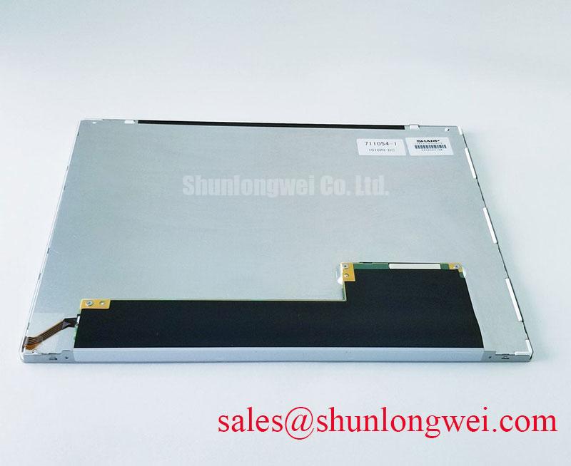
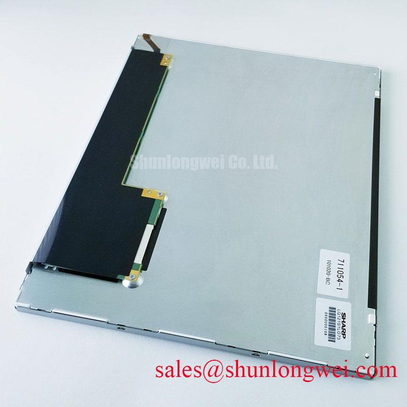
| Model | LQ121S1LG73 |
|---|---|
| Manufacturer | Sharp |
| Product category | Industrial grade LCD/HMI panel |
| Module technology | TFT-LCD active matrix color display module |
Display solid red, green, and blue test images on the LQ121S1LG73, and record any fixed bright points, dark points, or lines at the same screen coordinates. Use the equipment’s known-good image source and operating settings so that a source fault is not mistaken for a panel fault. Then display a uniform light field and a dark field to inspect background uniformity. Photograph each result at a consistent viewing position; changing the camera angle can make a viewing-angle effect look like a new defect.
If the screen remains dark while a recognizable image is being supplied, sweep a flashlight obliquely across the front surface while watching the affected area. A faint image visible under the flashlight suggests that image formation may be continuing without adequate backlight illumination. A sharply bounded line that remains in the same place across test images calls for a different check: compare the source output, cable seating, connector contacts, and panel input signals before attributing it to the display module. A flashlight test cannot establish a particular internal driver failure.
For a replacement evaluation, match the original assembly documentation for active area, resolution, mounting features, connector orientation, interface pinout, supply requirements, and backlight connections. The stated factory information identifies this model as a Sharp TFT-LCD module but does not establish those interface values. The system integrator should verify the required supply voltage from the original panel documentation. LQ6AW31K can be included in a cross-model comparison, but it is not a confirmed drop-in replacement on the basis of a similar display designation.
Backlight Startup and Driver Fault Checks Without Assuming a Lamp Type
Measure the display assembly’s backlight input at startup and compare the waveform with the original equipment schematic and a known-good unit. If the screen forms an image but remains unlit, separate the image path from the illumination path before removing the panel. Check connector seating, driver-enable behavior, supply stability, and any available fault output in the host equipment. A backlight that briefly illuminates and then switches off may reflect driver protection, a connection fault, or a problem in the illumination assembly; the shutdown sequence alone does not identify which one.
Do not select a high-voltage lamp supply or an LED constant-current driver from the model name. The verified specification supplied for LQ121S1LG73 does not state its backlight technology, ignition requirement, drive current, dimming method, or service-life rating. For a compatible driver assessment, trace the original assembly wiring and check the manufacturer documentation for the actual backlight and its control signals. LQ9D023 is a separate display product that may be useful in a system-level comparison; its electrical requirements must not be transferred to this module.
As a Design Consideration, inspect whether the host driver reports open-load, short-circuit, or overvoltage conditions before interpreting a dark screen as panel failure. Record the fault output alongside input voltage and enable state during startup. If the equipment uses dimming, assess visible flicker and driver noise at the operating settings specified for that equipment rather than imposing an unverified PWM frequency or dimming ratio on this panel.
Surface Readability and Mounting Stress in the Operator Enclosure
Inspect the displayed image under the operator station’s actual ambient lighting, then repeat the check after temporarily shading direct reflections. This distinguishes insufficient image contrast from glare introduced by the enclosure window or its position. The supplied factory parameters do not specify an anti-glare treatment, anti-reflective coating, LCD viewing mode, or viewing-angle limits for LQ121S1LG73; none should be assumed when choosing a replacement window or setting the operator’s viewing position.
Compare uniform-field images before and after fitting the bezel. If a bright patch changes with bezel pressure, inspect gasket placement, support points, and fastening sequence. As a Design Consideration, the seal should maintain contact without concentrating load on the display face; the enclosure drawing and panel mounting instructions determine the permitted compression and fastening method. Check that dust has not accumulated along the gasket edge or in the cooling path, where it can complicate inspection and temperature control.
⚠️ Maintenance Note: Disconnect power before reseating display cables, and inspect the gasket and cooling path during the same service visit.
A petrochemical operator station is one possible enclosure-compatibility evaluation, not an approval conferred by the LCD module. For a Zone 2 installation, the responsible equipment engineer should check the complete station’s applicable approval, window construction, sealing, and temperature limits independently. Sharp’s industrial display information provides broader manufacturer context; model-specific surface and mounting limits still need to come from the relevant panel documentation.
Pixel Jitter and Horizontal Lines Near Motor Drives
Capture the display input signals while the adjacent motor drive is stopped and again while it operates, noting whether pixel jitter or horizontal lines follow drive activity. Repeat the comparison at the source connector and the panel-side connector where the equipment design permits safe probing. A disturbance that appears only at the panel end points toward the cable path or its terminations; a disturbance already present at the source needs investigation upstream. Neither observation, by itself, proves that electromagnetic interference is the sole cause.
Inspect cable routing beside motor power wiring, connector retention, shield termination, and the enclosure bonding scheme. As a Design Consideration, preserve the interface’s specified signal geometry and return path while reducing coupling from drive wiring. If the original design uses differential signalling, determine its impedance and timing requirements from the host and panel documentation rather than assigning an unsupported target to LQ121S1LG73. Assess ferrites or changes to shield termination with the equipment’s electrical and EMC test plan; a panel alone does not establish system EMC compliance.
If lines or slow image transitions appear mainly after a cold start, log the ambient temperature and compare the same test image as the enclosure warms. Liquid-crystal response can change with temperature, while condensation can affect connectors and optical surfaces. Avoid treating a cold-start symptom as proof of panel damage: check the equipment’s permitted operating range, warm-up controls, and moisture management before deciding on corrective work. The Ultimate Guide to Industrial TFT LCD Technology provides background on these display behaviors; acceptance limits for this installation must come from its documented equipment requirements.