

Content last revised on October 15, 2026
Controlled Differential Impedance Routing to Reduce Display Link Disturbances
When an instrument shows diagonal tearing, intermittent pixel blocks, or a frame that appears divided into sections, begin with the display link rather than adjusting the image settings. Confirm that the replacement cable follows the original pair assignment, reference return path, connector orientation, and shielding arrangement. A differential link designed around 100 ohms requires the complete interconnect to maintain its intended electrical behavior; connector transitions, flex bends, branch stubs, and poorly bonded shields can change the effective impedance even when the PCB routing appears correct.
The host controller should be checked for its required logic supply, power-on rise profile, reset behavior, and video-enable sequence. The LQ150X1LG93 should not be connected on the assumption that an unverified 3.3 V or 5.0 V interface is interchangeable. The system integrator should use the original panel documentation and the equipment service records to confirm the required supply voltage, signal standard, pin assignment, and timing relationship.
JEIDA and VESA data mapping are not interchangeable labels. A panel can receive clock activity and still display incorrect colors when the source mapping does not match the panel configuration. Compare the red, green, and blue bit order, control signal polarity, clock edge, and blanking behavior with a known-good assembly. An oscilloscope comparison is useful when the image fault changes with cable position or instrument load, because it can reveal excessive ringing, common-mode disturbance, or clock instability without attributing the symptom to the panel alone.
Backlight evaluation belongs on the power side of the investigation. The driver should be checked for correct output regulation, enable behavior, dimming control, and thermal response according to the backlight specifications. A brightness life statement such as a 50,000-hour point to 50 percent brightness is a test-condition-dependent reliability metric and should not be assigned to the LQ150X1LG93 without the corresponding manufacturer test definition. For system-level display reliability guidance, engineers can consult Industrial Display & HMI Solutions.
Evaluating Frame Lag and Image Smearing in Cold Industrial Environments
At sub-zero temperatures, image transitions can become visibly slower because liquid-crystal response is affected by temperature, drive waveform, panel condition, and the surrounding thermal mass. When the LQ150X1LG93 is evaluated for an outdoor instrument or a storage environment, confirm its specified operating and storage temperature limits before testing. Record the image behavior during controlled temperature changes within the specified operating range instead of treating a temporary smear as a permanent panel defect.
Gray-to-gray response should be assessed using moving bars, alternating gray fields, and the actual graphics generated by the host instrument. A static color screen may appear normal while motion artifacts remain visible during waveform scrolling or measurement trace updates. Compare the result with the original panel at the same temperature and display refresh condition. The comparison should include startup behavior, transition after thermal stabilization, and recovery after returning to the normal service environment.
Inspect the panel perimeter, frame pressure, flex routing, and connector retention after thermal cycling. Uneven mechanical stress can change the appearance of a display fault and may be confused with response lag. Sealant condition should be evaluated for cracking, lifting, contamination, or loss of enclosure contact, but no specific epoxy formulation or sealing performance should be attributed to this model without a documented construction specification.
| Evaluation area | LQ150X1LG93 integration checkpoint |
|---|---|
| Product identity | Sharp TFT-LCD active matrix color display module |
| Product category | LCD module; confirm suitability for the intended industrial HMI application |
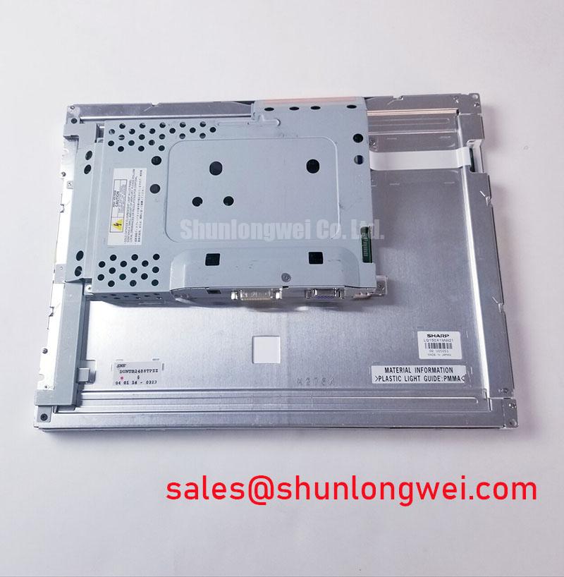
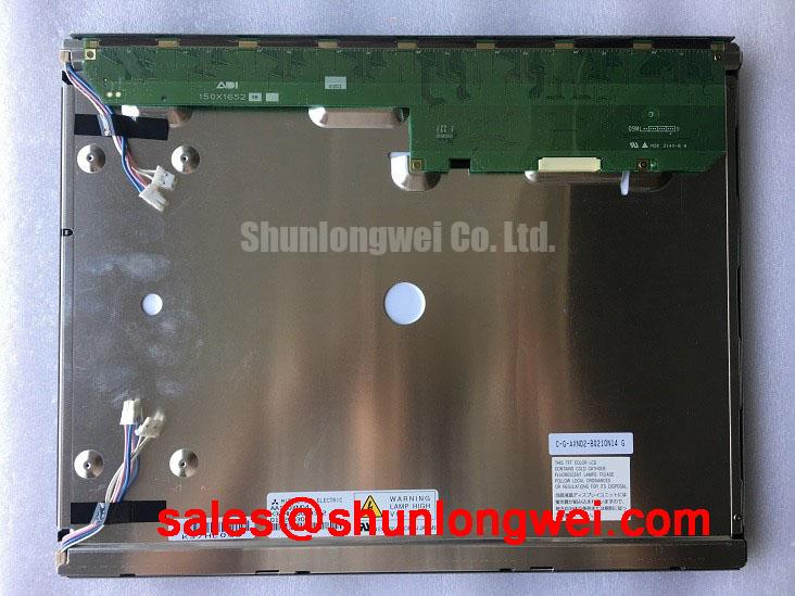
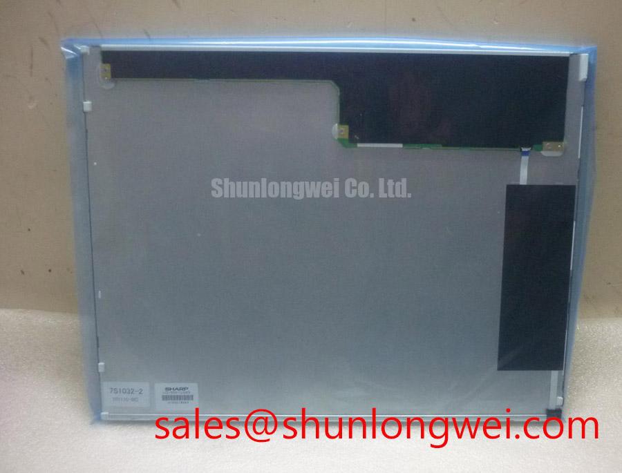
| Mechanical fit | Confirm equipment cutout and mounting interface against the module drawing |
| Electrical interface | Match the original panel documentation for supply, connector, mapping, timing, and backlight control |
Sharp’s industrial display resources at Sharp Devices Europe Industrial Display Solutions provide useful industry context for display integration and optical system evaluation. They should be read alongside the specific equipment documentation when assessing a replacement panel.
Incoming Benchtop Inspection: Display and Bond Integrity
Use a controlled color sequence to separate illumination faults from image-generation faults before installing the module into the instrument. A practical bench sequence is full red, full green, and full blue, followed by white and black fields generated by the known-good controller. Look for fixed vertical lines, repeated horizontal defects, missing color regions, localized dark areas, or changes that follow cable movement.
A flashlight held at approximately 45 degrees can help identify whether faint image information is present beneath an apparently dark screen. This observation is useful for separating a possible backlight or driver issue from a signal or pixel-addressing issue, but it is not a standalone failure verdict. Repeat the observation with the host backlight enable state, brightness control, and display cable condition recorded.
Accessible bonding areas should be viewed under uniform illumination without pressing on the glass or flex. Examine the perimeter for visible separation, contamination, crease damage, or localized line defects. A change produced by mechanical pressure is not a reason to press harder; it indicates that the module requires controlled handling and further comparison with the original assembly.
Bench tip: Disconnect power before inserting or removing the display cable, then verify connector keying and contact alignment before the next powered test.
For a precision electronic test instrument, document the color-field result, backlight state, host firmware image, cable identity, and temperature at the time of inspection. This creates a useful baseline for later comparison without assigning an unsupported field failure rate or service-life figure to the display module.
Surface Treatments and High Ambient Readability
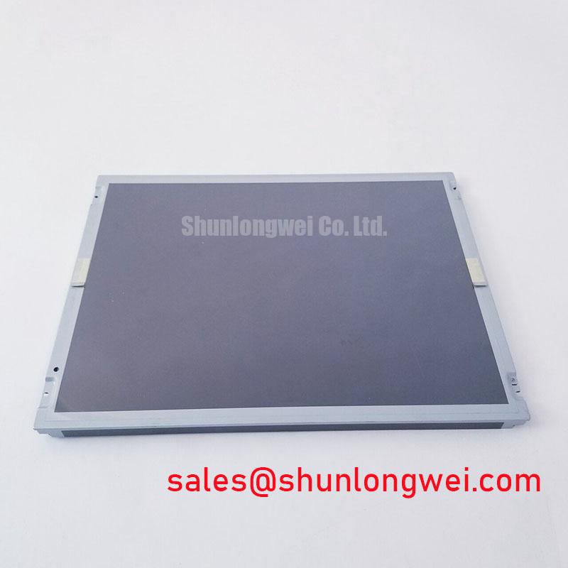
Readability in a brightly lit factory or field environment depends on the complete optical stack, including the panel surface, protective window, viewing angle, ambient reflections, graphics contrast, and enclosure geometry. Do not assume that an anti-glare or anti-reflective treatment is included in the LQ150X1LG93 unless the applicable panel documentation states it. A protective overlay can improve physical protection while also increasing reflections or changing touch interaction, so the installed assembly must be evaluated as a complete unit.
Viewing-angle behavior should be checked with the actual instrument screen, not only with a static white pattern. Observe fine text, waveform traces, alarm colors, and gray transitions from the operator’s normal position and from the expected side angles. TN grayscale inversion, IPS behavior, and MVA behavior are technology-specific characteristics; they should not be assigned to this Sharp model without a confirmed panel technology specification.
For high-EMI equipment, route differential pairs as a controlled transmission path through the full cable and connector structure. Keep pair geometry consistent, avoid unnecessary stubs, and maintain a continuous reference path through bends and enclosure transitions. The system designer should establish the impedance target, skew allowance, shielding method, and termination strategy from the host interface requirements, then verify the result with signal measurements under the actual servo, converter, or switching-noise conditions.
Outdoor and industrial readability also depends on the bezel opening, viewing window, mounting flatness, and tolerance stack. Check that the cutout does not load the glass, that fasteners do not distort the frame, and that the overlay does not obstruct the active area. The LQ150X1LG93 can be evaluated for operator displays in precision measurement and analysis equipment, subject to confirmation of the original mechanical drawing, electrical interface, optical requirements, and environmental installation conditions.