Content last revised on September 10, 2026
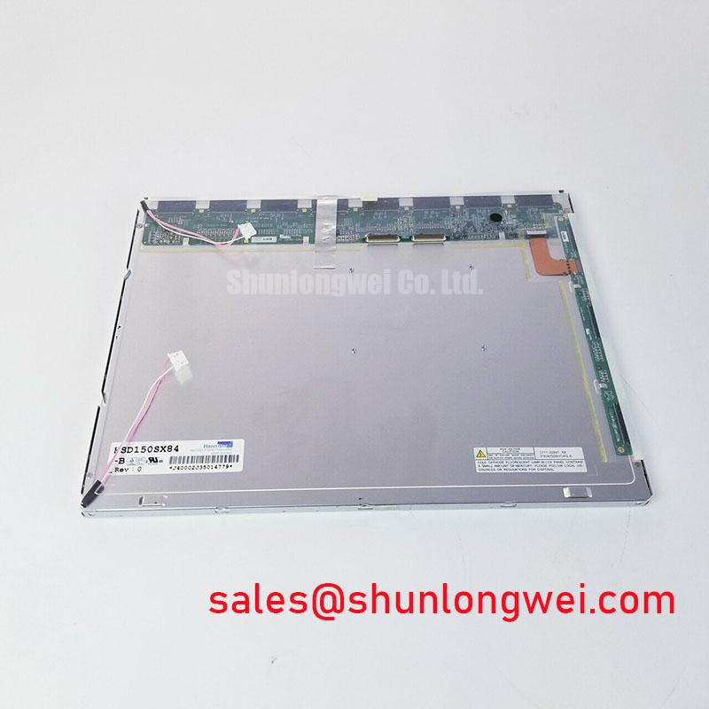
Before reconnecting the display cable, verify the panel label against HSD150SX84-A, inspect the LVDS connector for bent contacts, and confirm that the host controller is configured for an XGA panel rather than applying a generic display profile. This HannStar LCD module has an official 15.0-inch active display format, 1024×768 XGA resolution, one-channel 6/8-bit LVDS input, and WLED backlighting.
| Official Specification | Value |
|---|---|
| Screen size | 15.0 inches |
| Resolution | 1024×768 XGA |
| Brightness | 250 cd/m² typical |
| Contrast ratio | 700:1 typical |
| Viewing angle | 80/80/70/70 horizontal and vertical |
| Surface treatment | Antiglare |
| Display interface | LVDS, 1 channel, 6/8-bit |
| Backlight | WLED |
| Operating temperature | 0°C to 50°C |
| Storage temperature | −20°C to 60°C |
Optical Performance and Temperature Considerations
The 700:1 typical contrast ratio and 250 cd/m² typical brightness define the published optical baseline for HSD150SX84-A. Its antiglare surface treatment is useful where ceiling fixtures, console lamps, or nearby windows create reflected light on an operator-facing screen. Antiglare treatment can reduce disruptive reflections, but it does not replace an enclosure review when strong direct illumination is present.
The official viewing-angle specification is 80/80/70/70. It should be used as the relevant integration boundary rather than assuming the fully symmetric viewing behavior associated with other LCD technologies. For a substation protection or SCADA dispatch console, engineers should evaluate readability from the actual seated and standing operator positions, especially where several users view alarms from different angles.
Design Consideration: grayscale appearance and contrast can change as display temperature moves across the specified 0°C to 50°C operating range. Verify image quality at the anticipated enclosure temperatures with representative alarm screens, text, and low-contrast graphics. The LVDS transmitter must also match the panel’s one-channel 6/8-bit data format and timing requirements from the original panel documentation. Clock jitter, pair skew, data hold timing, and the selected JEIDA or VESA mapping are host-system responsibilities and should be checked with the configured controller rather than inferred from panel resolution alone.
💡 Pro Tip: Route each LVDS differential pair as a controlled, closely coupled pair with matched electrical length so pixel-clock timing is less exposed to noise and skew introduced by the display cable path.
Preventing Frame Lag & Image Smearing in Cold Storage & Outdoor Industrial Facilities
HSD150SX84-A is officially rated for operation from 0°C to 50°C and storage from −20°C to 60°C. It is therefore important to separate stored-condition checks from powered-operation qualification. Claims of acceptable powered operation at sub-zero temperatures, outdoor exposure, or extreme thermal cycling cannot be assigned to this model from the available official specifications.
Design Consideration: liquid-crystal response can slow as temperature declines, which may be visible as trailing or delayed grayscale transitions. Where a dispatch terminal is placed in an unconditioned cabinet or experiences cold delivery conditions, allow the panel and enclosure to stabilize within the stated operating range before judging motion performance. Check for moisture control and cable flexibility as part of the equipment-level assessment.
The module uses WLED backlighting, but no official backlight lifetime, brightness-retention curve, or current-driver rating is provided here. A constant-current LED driver should be verified against the original panel documentation, including its enable and dimming behavior. Avoid treating generic LED lifetime figures as a published service-life rating for this specific panel.
⚠️ Field Alert: Do not connect or remove the LVDS cable while the display system is energized, because transient contact sequencing can disturb the panel interface or host controller.
Full-Screen Primary-Color Screening: Stuck Sub-Pixels & Background Uniformity Audit
A practical receiving and repair bench check begins with full-screen red, green, and blue images, followed by white, black, and neutral gray patterns. Observe each pattern at normal viewing distance and from the operator’s expected angle. This method helps identify persistent bright or dark pixel behavior, color imbalance, line artifacts, and broad nonuniform areas without assigning an unsupported single cause.
For suspected backlight or optical-path issues, inspect a black image in a dim environment and use an oblique flashlight check around the bezel and enclosure opening. Uneven bright regions, shadowing, or light leakage may be associated with mechanical pressure, bezel interference, backlight behavior, or display assembly conditions. Repeating the test with a known-good LVDS source path can help distinguish a panel-visible issue from a timing or signal-integrity issue.
Image lines, intermittent color changes, or unstable frames may indicate a connection, cable, controller, or panel-level condition. Check connector seating, cable routing, grounding continuity, and the host LVDS output against a known-good path before replacing the module. The system integrator should verify the required supply voltage and power sequencing from the original panel documentation, because these values are not stated in the official parameters listed for HSD150SX84-A.
Mechanical Support and Thermal Management Along Display Edges
Mechanical integration should keep enclosure forces away from the visible area and avoid concentrated loading along narrow display edges. Design Consideration: if the host enclosure has nearby heat-generating electronics, evaluate whether a metal support rail, spacing strategy, or airflow path is needed to prevent localized heating near the LCD frame. Any thermal interface material must be selected and positioned by the system designer so it does not introduce pressure, contamination, or stress into the panel assembly.
WLED dimming quality depends on the compatibility between the system driver and the panel’s documented backlight-control requirements. A dimming waveform that produces visible flicker, unstable low-light output, or audible enclosure noise should be assessed at the complete equipment level. Verify the actual brightness behavior using the intended cable, controller, driver, and enclosure configuration.
When evaluating a different display for an existing assembly, physical dimensions, mounting geometry, interface assignment, resolution, brightness, and environmental ratings all require independent confirmation. The LMS700KF01-001 can be reviewed as a separate display option, but it should not be treated as a direct replacement without a documented mechanical and electrical compatibility check. For broader evaluation methods covering interface, optical, and environmental constraints, consult The Ultimate Guide to Industrial TFT LCD Technology.