

Content last revised on September 10, 2026
Assembly Integrity & Layout Architecture for GP370-SC41-24V
| Model | GP370-SC41-24V |
| Manufacturer | Pro-face |
| Product Category | Industrial LCD Operator Interface |
| Display | 5.7-inch Color STN LCD |
| Resolution | 320 × 240 pixels QVGA |
| Rated Supply | 24V DC |
| Touch Technology | Resistive Touch Screen |
| Communication Interfaces | RS-232C and RS-422 |
| Backlight | CCFL, User Replaceable |
| Typical Role | Industrial Automation and PLC Operator Interface |
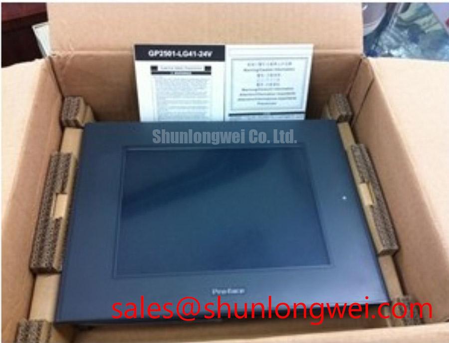
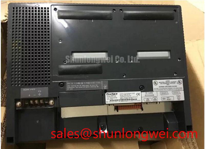
With the controller isolated from its 24V DC supply, inspect the GP370-SC41-24V front bezel, display window, touch surface, rear connector area, and mounting points for stress marks, loose retention hardware, corrosion, or a connector that has begun to back out from vibration. A 5.7-inch operator panel is often installed in a tight cabinet cutout, so a distorted bezel or uneven mounting pressure can create touch-position inconsistency, intermittent display behavior, or localized pressure marks on the Color STN LCD.
The GP370-SC41-24V is an industrial HMI display, not a power semiconductor or thyristor assembly. Parameters such as non-repetitive surge current, semiconductor junction temperature, firing angle, diode reverse recovery, and RC snubber sizing are not applicable specifications for this model. For a soft starter repair, those measurements belong to the separate power-stage components, while this Pro-face unit should be assessed as the operator interface responsible for presenting alarms, configuration pages, motor status, and commands.
The official hardware specification identifies a 320 × 240 pixel QVGA Color STN LCD with a resistive touch screen. During a replacement assessment, match the panel’s physical mounting arrangement, connector engagement, communication path, cabinet cutout, and operator-access geometry to the existing machine assembly. Resolution alone does not establish replacement compatibility because the PLC program, serial protocol settings, screen project, alarm mapping, and touch-coordinate calibration are system-dependent.
Inspect the flexible cable paths and connector locking features without sharply folding or pulling on attached harnesses. Repeated bending near a fixed connector, unsupported cable weight, or contact with an enclosure edge can introduce intermittent operation that resembles a software or communications fault. Design Consideration: secure the wiring path so vibration is not continuously transferred into the rear connector or any flexible interconnect associated with the display assembly.
Static process screens deserve attention in equipment that remains energized for long intervals. Color STN displays can show temporary image retention when a high-contrast screen, alarm banner, or fixed menu structure remains unchanged for extended periods. This should be treated as an operating and screen-design consideration rather than a published lifetime rating for this model. Where the original application permits, system engineers can evaluate screen-saving behavior, periodic interface changes, and appropriate brightness settings while preserving clear machine-state visibility.
The CCFL backlight is identified as user replaceable in the official product information. A dim image, uneven illumination, or a screen that remains visible only under strong external light can direct troubleshooting toward the backlight path, but these observations do not establish a single cause. Inspect the backlight condition, its related connector seating, supply stability, and the controller’s normal display output before replacing parts.
⚡ Safety Interlock Note: Disconnect and verify the cabinet power source before handling the GP370-SC41-24V, its serial wiring, or its replaceable CCFL backlight assembly.
GP370-SC41-24V Operational Boundaries and Serial Interface Verification
Measure the supply at the GP370-SC41-24V power connection while the machine is attempting to start the HMI, then observe whether the panel completes its normal display initialization or remains blank, partially lit, or intermittently reset. The official supply requirement is 24V DC; the system integrator should verify polarity, terminal assignment, source capacity, grounding arrangement, and switching behavior against the original machine documentation.
Power sequencing matters when an operator terminal shares a control supply with relays, contactors, PLC inputs, communication converters, or other cabinet loads. A display that appears normal at idle but resets during a motor-start command may point to a transient in the common control supply, a loose terminal, wiring resistance, or an issue elsewhere in the control architecture. Capture the voltage behavior at the HMI connection and compare it with a known-good path when available. This is an Engineering Recommendation for fault isolation, not an official transient immunity specification for the GP370-SC41-24V.
The supported serial interfaces are RS-232C and RS-422. These interfaces should be evaluated against the installed PLC, protocol converter, soft-starter controller, or supervisory controller. RS-232C and RS-422 have different signaling methods and cable practices; they should not be treated as interchangeable merely because both are serial interfaces. Confirm the original port selection, connector pin assignment, baud settings, parity, stop-bit configuration, termination arrangement where applicable, and screen-project communication settings.
LVDS differential-pair impedance, JEIDA and VESA pixel mapping, and TFT clock-skew budgets do not apply to the externally documented interfaces of this operator panel. The GP370-SC41-24V is specified with serial communications rather than a customer-accessible LVDS display input. Applying LVDS-oriented wiring assumptions to an RS-232C or RS-422 troubleshooting task can waste time and may lead to incorrect harness modifications.
For RS-422 communication, inspect the cable route for exposure to contactor coils, motor leads, soft-starter power wiring, and high-current switching paths. Design Consideration: maintain clear separation between low-level communication conductors and noise-generating power conductors, then validate the communication waveform and error behavior under the actual switching conditions of the cabinet. Shield termination and reference practices must follow the original equipment design because the correct arrangement depends on the overall control system.
💡 Pro Tip: Trace each serial conductor end to end and verify its terminal destination before changing protocol settings, because a crossed pair, incorrect reference connection, or misidentified port can imitate a controller configuration failure.
In a high-voltage three-phase motor solid-state soft starter, the GP370-SC41-24V can be evaluated as the local human-machine interface for configuration and status display. It should not be assumed to control firing-angle calculations, manage reactive power, or determine semiconductor commutation behavior by itself. Those functions remain dependent on the soft-starter control electronics, firmware, current sensing, gate-drive circuitry, and programmed control strategy.
Field Diagnostics & Commissioning for the GP370-SC41-24V Display Path
Inspect the screen under normal cabinet lighting and then under a controlled external light source to distinguish a weak backlight condition from low LCD contrast, incorrect display data, or a blank controller output. The official display technology is Color STN LCD with a CCFL backlight. No official contrast-ratio rating, sunlight-readable rating, anti-glare-coating specification, or CCFL brightness-life figure is provided in the stated product data, so no numeric optical or lifetime claim should be assigned to this specific model.
A screen that is faint but still contains recognizable menus may justify examination of the CCFL backlight path. A completely blank screen can also result from control power interruption, display initialization failure, damaged communications, an inactive controller, a cable issue, or a system configuration condition. Use observed behavior as a starting point for structured testing rather than assigning one visual symptom to one component failure.
Commissioning should verify the actual operator functions used by the machine rather than only confirming that the panel lights up. Review page navigation, alarm acknowledgment, numerical entry fields, touch response across the accessible active area, communications stability, and the intended PLC or soft-starter status indications. A resistive touch screen responds to physical pressure, and apparent loss of touch accuracy can be influenced by screen calibration, front-surface contamination, mechanical stress, incorrect project settings, or damage to the touch assembly.
When examining the touch surface, use a clean non-abrasive method suitable for industrial display equipment and avoid pressing with sharp tools. Inspect whether the panel responds consistently near edges and across routine operator controls. If a particular region does not respond, compare the behavior after verifying the machine project and calibration procedure. Do not force calibration changes when the underlying issue may be mechanical or communication-related.
Commissioning checks for display disturbance should include observation during switching events, motor-start sequences, and normal cabinet load changes. A panel that flickers or resets only when power equipment operates may indicate coupling through the control supply, grounding path, enclosure routing, or serial cable environment. The external power stage should be investigated independently for switching behavior, but reverse-recovery current, turn-off loss, and high-frequency device dissipation are not specifications of the GP370-SC41-24V display.
For broader display troubleshooting principles, including distinguishing image issues from backlight and interface issues, consult The Ultimate Guide to Industrial TFT LCD Technology. Although the GP370-SC41-24V uses Color STN rather than TFT technology, the practical discipline of separating optical symptoms, control signals, power integrity, and mechanical installation remains useful.
Industrial-display optical design and viewing conditions are also discussed by Sharp Display Solutions. Their resources provide useful industry context, but they do not establish product-specific optical ratings for the Pro-face GP370-SC41-24V.
Preventing Spurious Faults During GP370-SC41-24V Integration
Check the GP370-SC41-24V connector seating, serial cable routing, touch response, and display stability while the cabinet is operating through its normal command sequence, because intermittent faults often emerge only when control loads and communications are active together. The panel’s documented role is an industrial automation and PLC operator interface, so prevention work should focus on its 24V DC power path, RS-232C or RS-422 communication path, mechanical retention, and operator-facing display condition.
RC snubbers, saturable reactors, turn-on current-rise control, and dv/dt suppression belong to the motor soft starter’s power circuit and should be evaluated from that circuit’s approved design data. They are not integration settings for the GP370-SC41-24V. If an HMI issue appears when a soft starter begins operation, separate the investigation into two paths: assess the power-stage event with the relevant electrical test methods, and assess whether that event affects the HMI supply or serial communication environment.
The official specification states a CCFL backlight but does not specify PWM dimming frequency, dimming duty-cycle linearity, audible-noise behavior, or an external brightness-control interface. Do not impose a generic PWM dimming scheme on this model without confirming the original panel and machine design. When a backlight service action is required, use the established replacement method for the installed equipment and inspect the resulting illumination and display readability under normal operating conditions.
Mechanical installation should allow the HMI enclosure to sit flat against its intended mounting surface without twisting the display body. Design Consideration: use the original enclosure hardware and mounting approach so the front panel remains evenly supported and the rear wiring does not apply continuous leverage to the terminal area. Cabinet vibration, repetitive door movement, and unsupported cable loops can affect long-term connector reliability even when the display initially operates normally.
Cold-start response, delayed screen updates, and residual images after a power interruption should be recorded as observable behavior and compared with the known machine sequence. The stated official parameters do not include a wide-temperature operating range, cold-start timing, display-response-time curve, or power-down retention specification. Engineers should therefore validate actual installation conditions against the original equipment requirements rather than assigning unsupported environmental limits to the GP370-SC41-24V.
For procurement and repair planning, retain the model designation GP370-SC41-24V, the Pro-face brand reference, the 5.7-inch Color STN display description, 320 × 240 pixel resolution, 24V DC supply rating, resistive touch interface, RS-232C and RS-422 communications, and user-replaceable CCFL backlight requirement. These documented identifiers provide a practical basis for assessing mechanical, electrical, communication, and operator-interface compatibility without inferring unsupported system-level characteristics.