



Content last revised on September 19, 2026
SV24-28-350 Circuit Protection & Reliability: Calibrating Turn Off di/dt Induced Vpeak Clamping
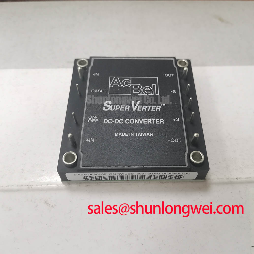
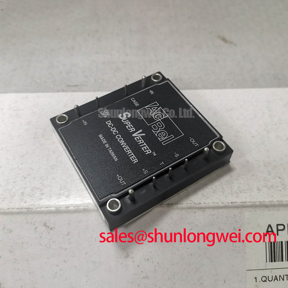
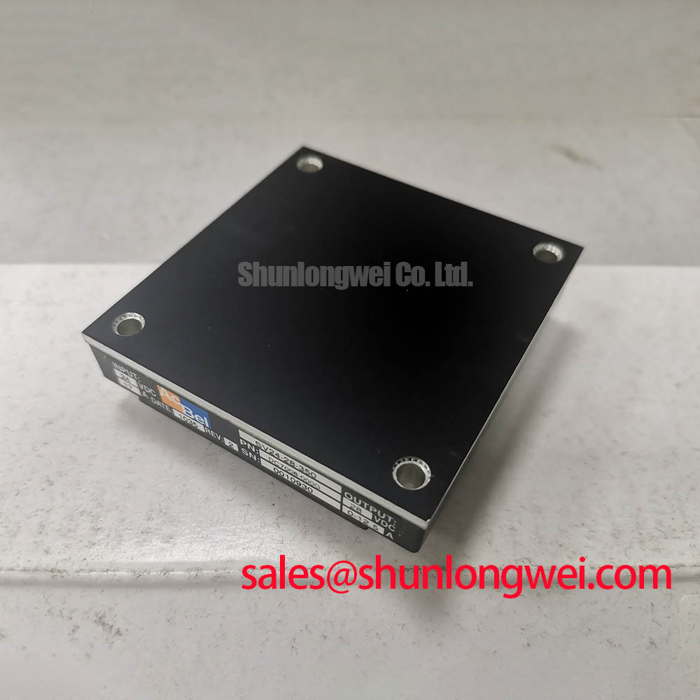
Before energizing a replacement assembly, inspect the SV24-28-350 brick module for damaged terminals, enclosure distortion, residue around the mounting interface, and signs that the surrounding harness has been pulled or overheated. Confirm the equipment bill of materials and original power schematic before treating this Vicor unit as electrically interchangeable with another brick format.
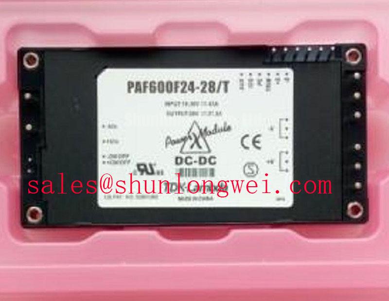
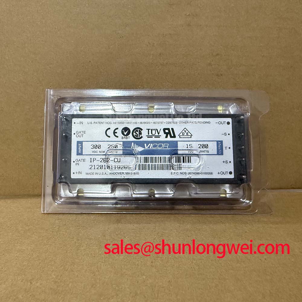
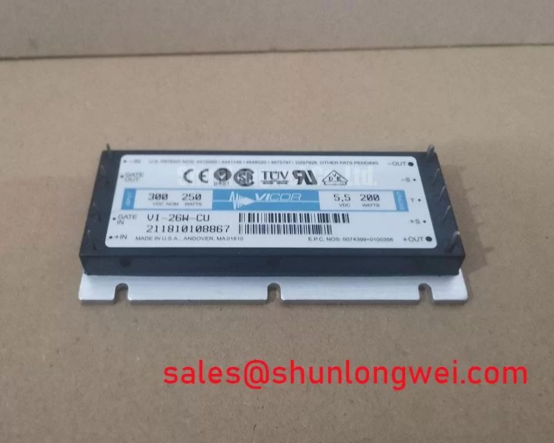
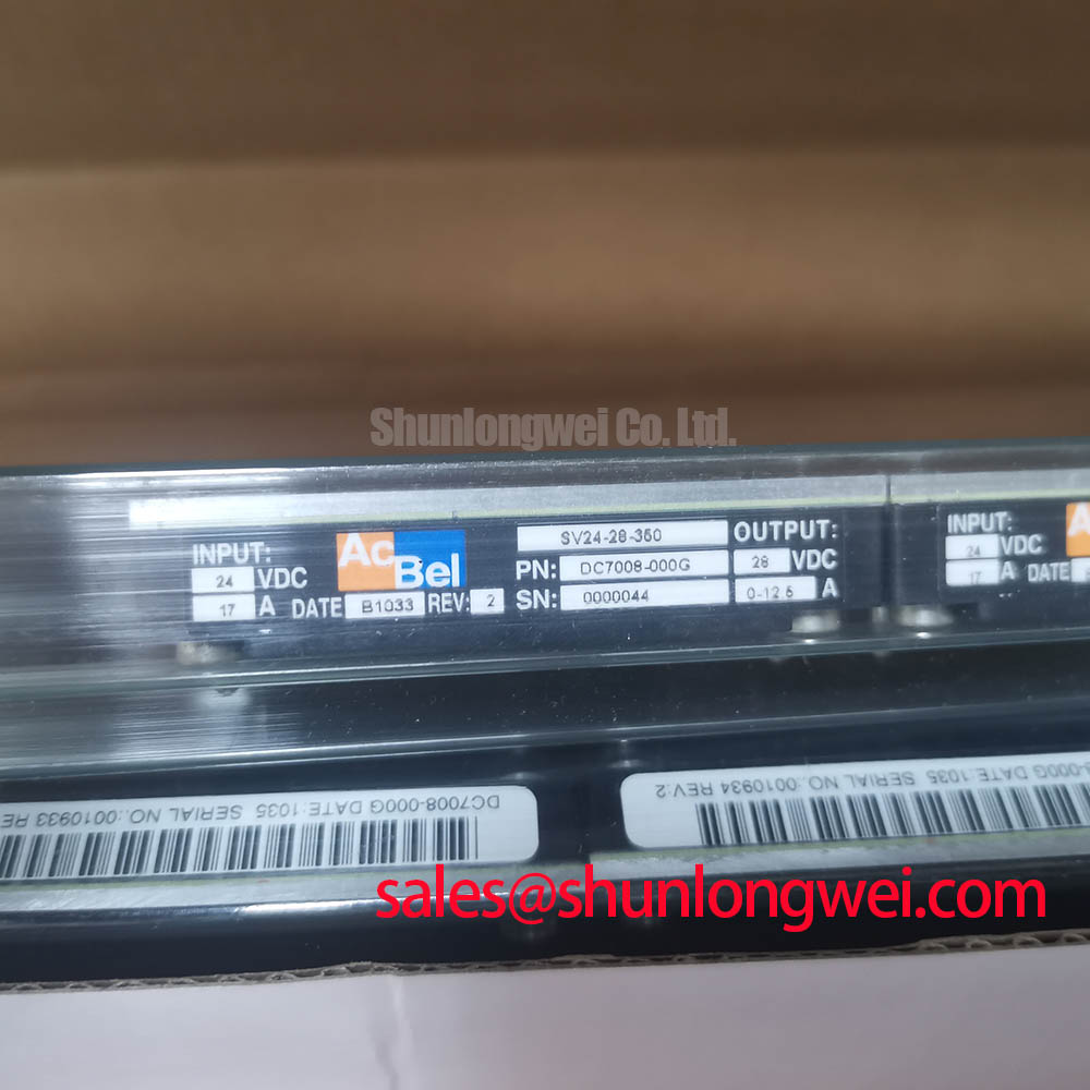
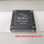
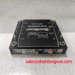
The documented product identity is a Vicor Brick Module power unit with a 5.0A current rating. Its working-voltage description is Standard Industrial Rating. These are Official Specifications. The available product information does not establish an internal IGBT switching stage, a braking transistor, a freewheeling diode, an allowable switching-frequency range, or a specified clamping voltage. Service teams should therefore avoid assigning inverter switching limits to the module itself.
| Item | Declared value | Status |
|---|---|---|
| Model | SV24-28-350 | Official product identification |
| Manufacturer | Vicor | Official product identification |
| Current rating | 5.0A | Official Specification |
| Package | Brick Module | Official Specification |
| Working-voltage description | Standard Industrial Rating | Official Specification |
In a forklift traction controller, turn off overshoot is usually an inverter power-loop concern. Its peak voltage is influenced by DC link voltage, loop inductance, and current slew rate. That relationship is an Engineering Calculation when supported by measured inductance and a captured switching waveform, not a published performance claim for the SV24-28-350. Engineers investigating a high-voltage event should measure the actual switching nodes at the inverter, correlate the event with load current and gate timing, and then confirm whether the converter input path is being disturbed by the same event.
As a Design Consideration, keep the DC link loop compact where an inverter is present, preserve the intended clearance and creepage distances of the original assembly, and inspect capacitor connections for movement caused by vibration. A snubber should only be selected after waveform capture and thermal verification. Adding a capacitor or changing a damping network without confirming resonance can shift stress elsewhere in the power stage.
When a controller design is being compared against a different power-semiconductor assembly, the P950A can be reviewed as a separate product reference. Matching a part number family, terminal position, mechanical outline, input requirements, output requirements, and control behavior remains necessary before any replacement decision. Similar packaging alone does not establish functional compatibility.
Benchtop Waveform Tuning: Mitigating Stress via Optocoupler vs Digital Coreless Transformer on SV24-28-350
Bench work should begin with the converter disconnected from unnecessary loads and with the original equipment documentation available. Verify the input source, output destination, connector orientation, enable behavior, and protective grounding arrangement before connecting measurement equipment. The SV24-28-350 is identified as a 5.0A Brick Module; its published information supplied here does not specify an isolated gate-drive interface, reinforced isolation rating, common-mode transient immunity, or optocoupler and digital-transformer architecture.
Optocouplers and digital coreless transformers are generally evaluated at the gate-drive boundary of a switching inverter, where false turn-on can occur if common-mode noise reaches the control reference. This is a Design Consideration for the surrounding traction inverter, not an attribute that should be attributed to the Vicor module without manufacturer documentation. Probe the control and power domains with an appropriate differential measurement method, compare behavior to a known-good channel where available, and determine whether a disturbance begins in the driver, the DC link, the motor cable, or the logic supply.
Reverse recovery behavior of a freewheeling diode can affect ringing and radiated emissions in a motor inverter. It is not appropriate to assign a recovery softness factor or diode characteristic to the SV24-28-350 from its brick-module designation. Where motor-current commutation is under review, capture voltage and current together, inspect the timing of the diode recovery interval, and verify whether the observed ringing changes with cable routing, load state, or busbar condition. Any resulting gate resistance, snubber network, or shielding adjustment should be treated as an Engineering Recommendation validated on the finished system.
Power conversion faults can also originate ahead of the low-voltage control supply. In equipment using a separate rectifier or power-semiconductor stage, the MG150Q1JS40 may be examined as a distinct upstream device reference. It should not be presumed to be an integrated companion or replacement for the SV24-28-350.
For routine maintenance, inspect cooling-air paths, remove accumulated dust using the site-approved method, and review thermal interface materials for age-related hardening or displacement. Maintenance Note: Check terminal contact temperature during normal duty and confirm that the cooling path remains unobstructed before returning the equipment to service.
Field Diagnostics & Commissioning: Output Sinusoidal Filter vs dv/dt Reactor in SV24-28-350 Topologies
When commissioning a repaired forklift or warehouse-vehicle controller, first separate the low-voltage control-power investigation from the traction-output investigation. Confirm whether the SV24-28-350 output remains stable under the equipment's intended control load, using the original documentation to establish the required voltage and sequencing conditions. The supplied official data establishes the 5.0A rating but does not state the output voltage, output ripple, transient response, pinout, regulation method, or protection thresholds. The system integrator should verify these requirements from the original panel documentation and approved Vicor data.
Long motor leads can behave as transmission lines and can create reflected voltage events at the motor terminals. A dv/dt reactor and a sinusoidal filter address different system conditions, so neither should be selected as a universal correction. This is a Design Consideration for the motor drive output. A reactor may be evaluated where edge-rate control is required, while a sinusoidal filter may be evaluated when motor-terminal waveform quality and cable behavior require broader attenuation. The final choice depends on the inverter, cable construction and length, motor insulation system, switching behavior, and measured terminal waveform.
Symptoms such as unstable control logic, intermittent display behavior, nuisance controller resets, or unexpected drive trips do not establish a single cause. Check supply rails under realistic loading, inspect connector retention, review ground returns, and compare the measured signal path with a known-good system when possible. An oscilloscope capture can help distinguish a supply disturbance from an impedance mismatch or control-path noise event. Avoid interpreting a meter reading alone as proof of converter health when the fault occurs only during traction acceleration or regenerative braking.
Capacitor condition deserves attention because elevated equivalent series resistance can increase ripple-related heating and alter how a DC link responds to changing load. The relationship between resistance and ripple current is described in this reference on capacitor equivalent series resistance and ripple current. Use that principle to guide inspection of the complete power path, while retaining the distinction between general circuit behavior and a documented SV24-28-350 specification.
SV24-28-350 Thermal Electrical Optimization: Regenerative DC Bus Voltage Surge Dissipation Practical Tuning
During preventive maintenance, inspect the converter mounting surface, surrounding heat sink, airflow route, terminal tightness, and enclosure seals before assessing regenerative events. Moisture, condensation, blocked airflow, or aged thermal interface material can each affect assembly reliability, but no specific temperature range, ingress rating, mounting torque, thermal resistance, or operating-life figure should be assigned to the SV24-28-350 without the relevant official documentation.
Regenerative DC bus voltage rise is generated by the motor and inverter system when deceleration returns energy toward the DC link. The braking switch and ballast resistor, where fitted, belong to the system-level energy-management design. Their ratings must be determined from the actual vehicle mass, motion profile, deceleration demand, battery acceptance condition, DC link configuration, and measured energy flow. The Vicor module's supplied information does not identify it as an internal braking IGBT, a braking resistor controller, or a regenerative clamp.
For electric material-handling and forklift low-voltage traction systems, a practical commissioning sequence is to observe the DC link, auxiliary supply, and controller behavior during controlled acceleration, lift operation, travel deceleration, and idle recovery. Record the event conditions rather than assuming that a voltage excursion is caused by one device. Inspect whether the battery-management system, contactors, DC link capacitors, braking path, motor controller, and low-voltage supply are responding in the expected order. State-of-charge and state-of-health logic can also affect how an energy-storage system accepts regenerative energy; this overview of state of charge provides relevant system context.
Where long-term power-stage efficiency and switching verification are being evaluated, Unlocking Efficiency in Industrial Drives provides a separate technical reference for industrial-drive switching topics. It does not replace the official documentation required to validate the SV24-28-350 connection, electrical limits, or thermal installation in the repaired equipment.