Content last revised on September 10, 2026
NEC NL12880BC20-07F Replacement Identification
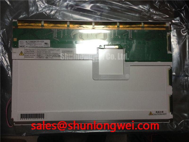
Before removing the existing panel, record its connector orientation, mounting position, visible identification label, and system wiring, then compare those observations with the NEC NL12880BC20-07F replacement documentation.
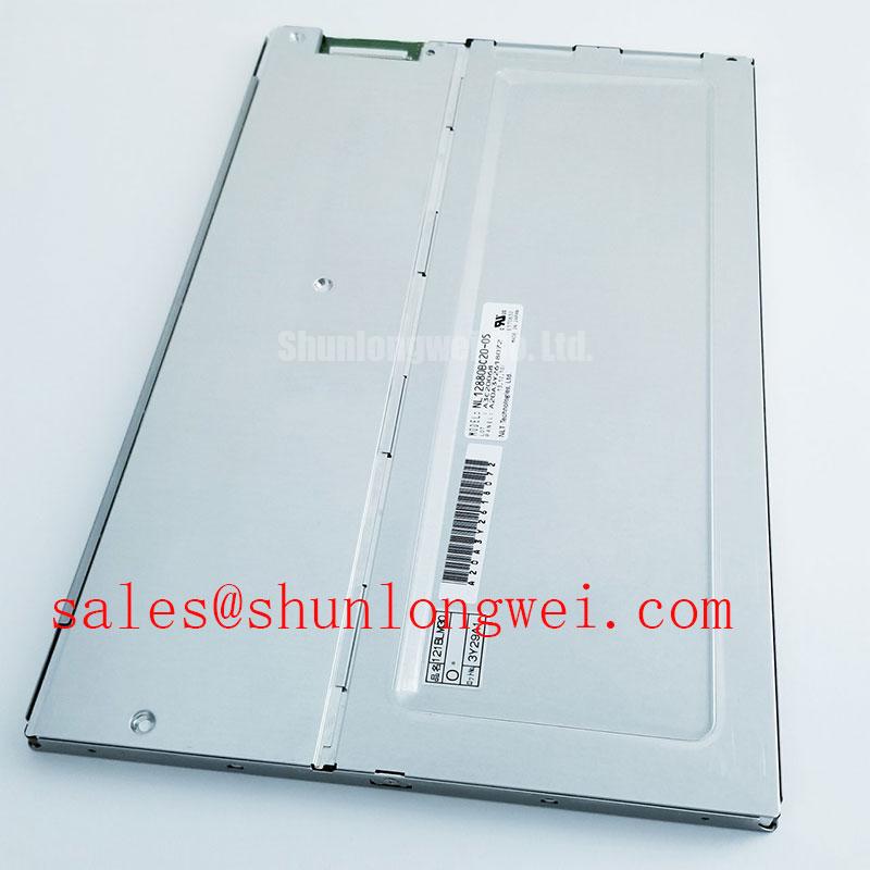
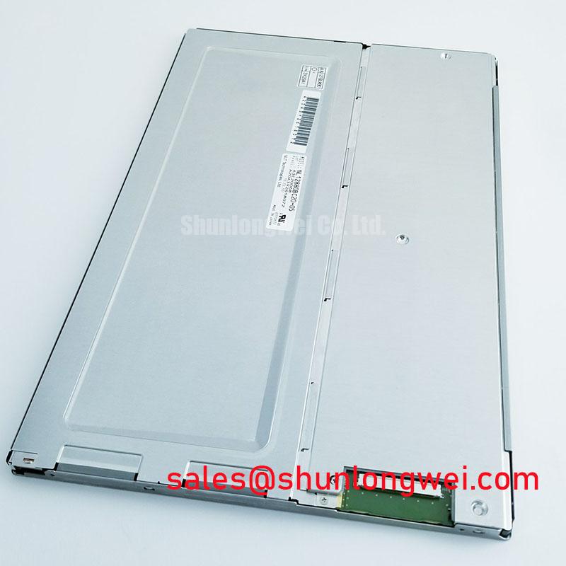
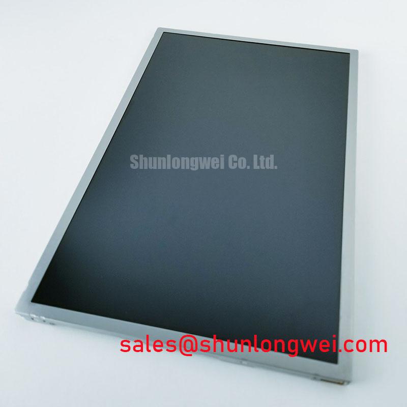
The NL12880BC20-07F is identified in the supplied factory information as an industrial grade LCD/HMI panel manufactured by NEC. Its stated package is a TFT-LCD display module, and its specification status is marked as Official Factory Spec Verified. The available product data does not confirm a complete electrical interface, native resolution, luminance rating, backlight technology, touch function, operating temperature range, or mechanical drawing. Those items must be checked against the original panel documentation and the equipment service records before installation.
| Model | NL12880BC20-07F |
| Manufacturer | NEC |
| Product category | Industrial Grade LCD/HMI Panel |
| Package or enclosure description | TFT-LCD Display Module |
| Specification status | Official Factory Spec Verified |
Optical Luminance Degradation Curve and Backlight Retrofit Assessment
Start a replacement assessment by separating the display module from the backlight and driver assumptions in the host equipment. The supplied factory data identifies the NL12880BC20-07F as a TFT-LCD display module, but it does not verify whether a particular installation uses a CCFL assembly, an LED assembly, an external inverter, or an integrated constant-current driver. The system integrator should verify the required backlight technology from the original panel documentation rather than applying a generic retrofit circuit.
A CCFL installation requires the technician to treat the inverter output as a high-voltage circuit during operation and after shutdown. A reported cold-ignition value such as 1500 to 1650 Vrms must not be attributed to this NEC model without a model-specific electrical source. If the original equipment uses CCFL, inspect the inverter connector, lamp wiring, insulation, and any evidence of arcing before condemning the LCD module. A replacement panel with a different backlight architecture may require a different power interface, enable signal, dimming method, or protection strategy.
LED modernization also needs a controlled comparison. Constant-current operation can provide stable optical output when the driver, LED string voltage, enable logic, and thermal path are correctly matched. PWM dimming capability, including a proposed 1000 to 1 range, is a system-driver characteristic and is not confirmed as a factory specification for the NL12880BC20-07F. Designers should verify the driver control method, minimum duty behaviour, startup sequence, open-string response, short-circuit response, and fault output at the equipment level.
Brightness decline should be recorded as measured optical data rather than presented as a guaranteed service-life curve. A commonly quoted 50,000-hour point to 50 percent brightness cannot be assigned to this model without a supporting NEC datasheet, test report, or qualified reliability document. It may be used only as a comparison criterion when evaluating a proposed LED retrofit. The test plan should define the measurement location, drive current, ambient temperature, duty cycle, and thermal conditions so that old and replacement assemblies are compared consistently.
Acoustic buzz, intermittent ignition, or visible flicker requires inspection of the complete backlight circuit. Check the driver output with suitable high-voltage instruments, confirm connector seating, and compare the enable and dimming signals with a known-good unit. If the display image is present but unevenly illuminated, isolate the backlight path before replacing the TFT module. A compatible option in a related NEC display family can be reviewed at NL128102BC28-04, but its interface and optical characteristics must be verified independently.
For AGV and forklift telematics displays, optical evaluation should include the actual cabin lighting, viewing distance, protective window, and expected contamination on the front surface. Strong sunlight, dust, and reflections can make a serviceable panel appear defective. The available data does not confirm an anti-glare or anti-reflective surface treatment for the NL12880BC20-07F, so AG and AR performance should be checked from the original documentation or by inspecting a sample in the target enclosure.
Normally White TN Behaviour, Viewing Direction, and Signal Integrity
Do not assume the panel technology from the model number alone. TN, IPS, and MVA viewing behaviour differs substantially, and the supplied factory information does not state the optical mode, viewing-angle values, native resolution, contrast ratio, or normally white operating condition for this model. When an AGV or forklift display is mounted at an angle to the driver, evaluate the actual image from the installed viewing direction instead of relying on a nominal viewing cone from another panel family.
Grayscale inversion, colour shift, or loss of shadow detail can be influenced by viewing angle, source timing, temperature, protective glass, and image-processing settings. A bench check should display white, black, red, green, blue, and several neutral grayscale patterns. Observe the panel from the planned operator position, then from the upper, lower, left, and right service angles. If a defect changes with viewing direction, document that behaviour separately from defects that remain fixed on the glass.
When the host uses a differential display interface, the integrator should verify the exact connector pinout, signal polarity, clock arrangement, power rails, enable sequence, and logic levels from the original panel documentation. A 100 ohm differential impedance target with a 10 percent tolerance is a common high-speed design consideration, not an official specification confirmed for the NL12880BC20-07F. The same applies to a 50 ps skew budget. Cable construction, connector geometry, board routing, common-mode behaviour, and the transmitter receiver pair determine the acceptable margin.
In a factory containing servo drives, switching contactors, and variable-frequency motor controllers, inspect the display cable routing before changing the panel. Keep sensitive signal wiring separated from high-current switching paths where the cabinet design permits, maintain the intended shield termination, and confirm that the display ground arrangement matches the equipment design. These are system-level EMC design considerations. The LCD module itself must not be described as independently certified to CISPR, EN 55011, or any complete-machine EMC requirement.
If the panel shows intermittent image loss, compare the suspected unit with a known-good signal path using an oscilloscope appropriate for the interface. Look for unstable clock activity, excessive ringing, missing enable transitions, or a change in common-mode voltage. A blank image may also result from the host controller, power sequencing, cable assembly, or backlight state, so the observation should be recorded without assigning a single cause prematurely.
For applications where the original screen size and resolution are the main selection constraints, engineers can also review NL8048AC19-13KD as a separate comparison item. It should not be treated as a direct substitute until the mechanical envelope, optical orientation, connector system, timing requirements, and power arrangement have all been checked.
Glass Substrate Handling and Driver-Bump Stress Prevention
Remove the old display with support across the panel frame rather than lifting from one corner. A TFT-LCD module is sensitive to twisting loads, point pressure, connector strain, and uneven bezel compression. The supplied data confirms the TFT-LCD module category but does not disclose internal driver construction, glass thickness, chip-on-glass details, or bump geometry. Maintenance personnel should therefore avoid assigning a particular internal fracture mechanism without physical evidence.
A practical three-stage colour bench check begins with a full white screen to reveal broad luminance non-uniformity, followed by red, green, and blue screens to expose colour-channel irregularities, and then black or neutral patterns to identify fixed defects and leakage. Record whether the defect moves with the image, remains at a fixed glass location, appears only after warm-up, or changes when the backlight is adjusted. This record helps distinguish an optical illumination issue from a display-data or glass-related issue.
A flashlight inspection can be useful when performed at approximately a 45-degree angle in a controlled environment. Use it to look for dark shadows, local reflections, frame pressure marks, and regions where the image changes when the backlight is disabled. The method is a troubleshooting aid, not a certified diagnostic test. Avoid pressing the front surface, flexing the frame, or repeatedly reconnecting the cable while power is applied.
Connector work deserves the same care as glass handling. Isolate power, discharge the equipment according to its maintenance procedure, and verify that the host controller is inactive before removing the display cable. Inspect contacts for contamination, check the locking mechanism, and make sure the cable enters the connector squarely. If a replacement produces a stable backlight but no image, compare the host output, timing, and enable conditions with the original assembly rather than assuming a panel fault.
TTL and LVDS timing values, transmitter clock jitter margins, data hold times, and industrial temperature limits are not provided in the supplied official parameter set. They must be obtained from the applicable panel documentation or measured against a verified operating unit. Designers should validate timing across the intended environmental range because a display that works on a cool bench may behave differently after cabinet heating, vibration, or repeated power cycling.
Maintenance Note: Disconnect cabinet power before inserting or removing the display cable, and inspect the cable lock and bezel support during every planned service visit.
Thermal Cycling, Condensation Control, and Gasket Integrity
Mounting preparation should begin with a clean, flat support surface and an inspection of the enclosure seal. Dust trapped under a gasket can create a local gap, while uneven fastener loading can transfer stress into the display frame. The correct fastener type, compression, mounting dimensions, and tightening method are system-specific because the supplied factory data does not include a mechanical drawing or gasket specification for the NL12880BC20-07F.
Temperature changes in an AGV or forklift cabin can produce condensation when a cold display is exposed to warm humid air. Before applying power, allow the assembly and enclosure to reach a stable condition under the equipment maintenance procedure. Inspect for moisture near the connector, front seal, cable entry, and protective window. Do not interpret a temporary slow image response during a cold transition as proof of permanent panel damage; document the temperature and recovery behaviour first.
Liquid-crystal viscosity, polarizer behaviour, adhesive response, and sealant performance can all influence cold-start operation, but the supplied information does not specify a qualification range such as minus 30 to plus 85 degrees Celsius for this model. That range must not be presented as an NL12880BC20-07F rating. If the host equipment requires such cycling, the system owner should obtain the original environmental specification and confirm that the complete display assembly, gasket, cable, and enclosure have been qualified together.
Gray-to-gray response variation at low temperature should be evaluated with moving test patterns, not with a single still image. Record the time from power application to usable image, note any transient colour shift or image retention, and repeat the test after the assembly has stabilised. The result can then be compared with the equipment’s operator requirements. Do not claim a specific GTG value unless it is supplied in the manufacturer’s data for this exact model.
Backlight reliability during thermal cycling also depends on driver current regulation, LED junction temperature where applicable, board heat spreading, and enclosure airflow. The proposed 50,000-hour half-brightness figure is not verified for the NL12880BC20-07F and should not be used as a guaranteed MTBF or lifetime statement. A qualification plan should measure brightness, startup behaviour, uniformity, and fault response under the actual duty cycle.
During final installation, verify that the bezel does not contact the active viewing area, the gasket follows a continuous path, and the cable is not pulled against the connector. For equipment exposed to vibration, designers should evaluate fastener retention and cable strain relief as part of the complete enclosure design. The Industrial Display and HMI Solutions reference can support broader enclosure and maintenance planning, while model-specific electrical and mechanical decisions should remain tied to the original NEC documentation.