


Content last revised on September 10, 2026
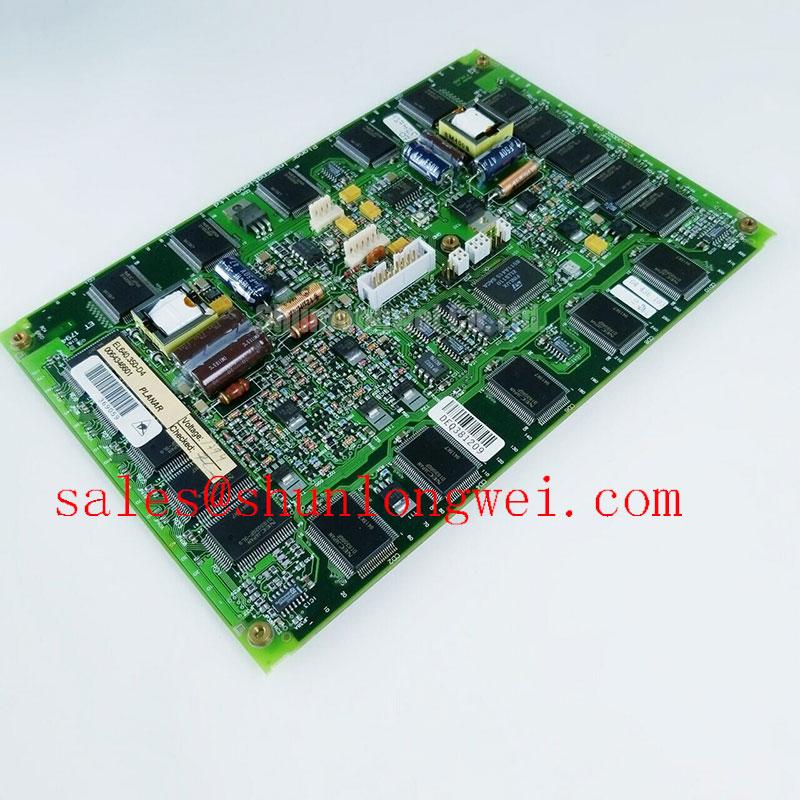
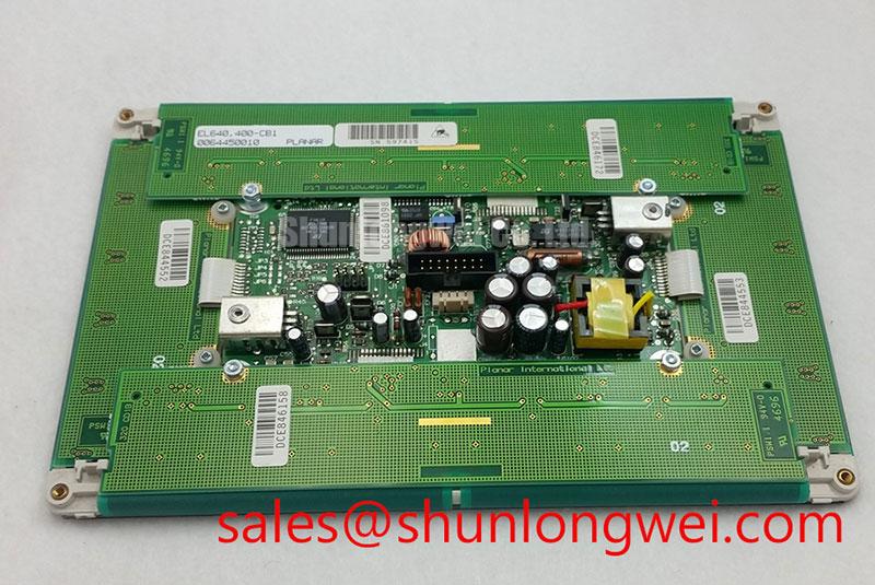
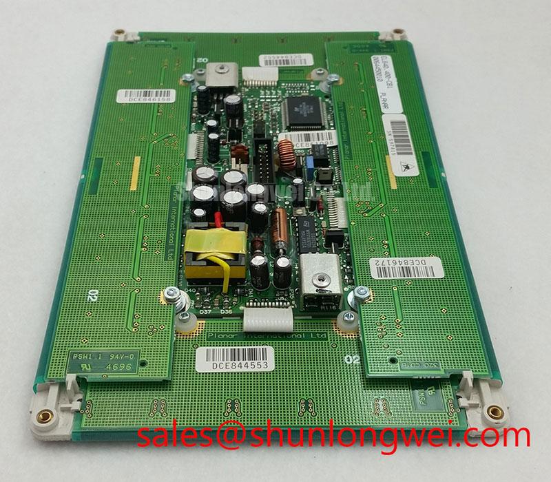
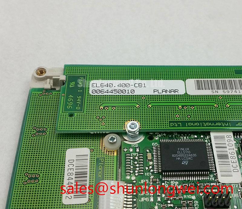
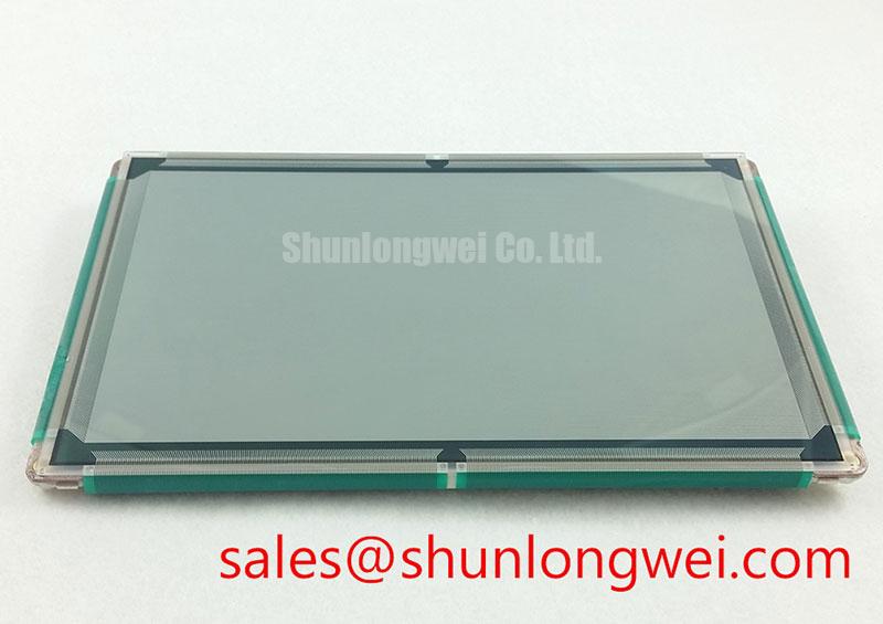
EL640.400-CB1 Inspection and Specification Verification
Place the EL640.400-CB1 on an ESD protected bench, inspect the TFT viewing area under uniform white, red, green, blue, and black patterns, then confirm that the display cable seats squarely without twist or side load before applying power.
| Item | Available Product Information |
|---|---|
| Product model | EL640.400-CB1 |
| Manufacturer | Planar |
| Product category | Industrial Grade LCD/HMI Panel |
| Module format | TFT LCD Display Module |
| Specification status | Product identification verified; detailed specifications require confirmation from the original documentation |
The EL640.400-CB1 is identified as a Planar industrial TFT LCD display module. Its exact electrical interface, input supply requirement, timing requirements, optical characteristics, mounting arrangement, and backlight configuration should be verified against the original equipment documentation before a replacement is connected. This matters especially in repair work, where a mechanically similar panel can still have a different signal mapping or power sequence.
Preventing Frame Lag & Image Smearing in Cryogenic Storage & Outdoor Industrial Facilities
Begin cold environment assessment by observing a stable image while the panel, cable, and controller are at the actual expected ambient condition. Liquid crystal response can slow as temperature falls because the material becomes more viscous. On a live HMI, that behavior can appear as delayed menu redraws, trailing edges around moving graphics, or a momentary difference between rapidly changing gray areas. These observations should be separated from controller timing faults by comparing the same video source with a known good display path where possible.
The EL640.400-CB1 product identification confirms an industrial TFT LCD display module, but no specific operating temperature range, Gray to Gray response figure, or thermal cycling rating is stated in the supplied factory data. Therefore, operation across the proposed minus 30°C to plus 85°C environmental span is a Design Consideration rather than an official rating for this model. The system integrator should verify the original Planar documentation and the final enclosure conditions before applying the panel in refrigerated storage equipment or exposed outdoor industrial stations.
Where an enclosure uses controlled heating, the practical inspection point is image behavior after the assembly has stabilized, rather than immediately after power is applied. A heater strip, thermostat, display controller, and cable route all belong to the host system and require system level validation. Check whether smearing reduces as the local panel temperature rises, then inspect the perimeter edge and mounting arrangement for stress caused by repeated expansion and contraction. Do not interpret a slow image alone as evidence of a panel fault.
For CNC operator panels and robot teach pendants, environmental suitability also depends on front overlay sealing, enclosure ventilation, and how tightly the display is constrained by the bezel. These are integration conditions, not verified characteristics of the EL640.400-CB1 itself.
Controlled 100 Ohm Differential Impedance Flex Routing to Suppress High Frequency Jitter
Inspect the existing display harness before removing the original panel. Look for a flex cable that is sharply folded, locally creased, contaminated at the contact area, or pulled away from its strain relief. A screen that intermittently shows split image regions, unstable pixels, or brief synchronization loss may involve the source board, cable seating, connector wear, or signal integrity. A controlled comparison with the original cable path and a known good controller output is more useful than assigning a single cause from the visible symptom.
A 100 ohm differential impedance route is a common Design Consideration for differential display interfaces when the applicable interface specification requires it. It should not be treated as a confirmed interface specification for the EL640.400-CB1. The system integrator should verify the original panel documentation for the required data standard, including whether the source uses JEIDA or VESA mapping, the approved cable arrangement, and the required logic supply voltage.
The supplied factory information does not confirm whether this specific model requires a 3.3 V or 5.0 V logic supply, nor does it confirm a defined power on rise time. Verify the required supply voltage and power sequencing from the original panel documentation. During a repair, scope measurements should be taken against the known good signal path where available, with attention to supply stability, clock and data continuity, grounding, and the timing relationship between panel logic and backlight enable.
Backlight brightness reduction is also a system level maintenance question. A 50,000 hour brightness to 50 percent figure is often cited in broader LED display discussions, but it is not an official lifetime specification provided here for the EL640.400-CB1. Evaluate actual luminance, screen uniformity, driver current regulation, and thermal conditions rather than applying a generic lifetime value to this unit.
💡 Bench Tip: Disconnect power before handling the display cable, use ESD controls, and lock the flex connector only after the cable is fully aligned and seated evenly.
Surface Anti Glare & Anti Reflective Etched Coating for High Ambient Readability
Use a controlled viewing check before judging readability. Display white, mid gray, black, and primary color screens, then inspect the panel from the normal operator position and from the expected off axis positions. Reflections from overhead lighting, window glare, protective windows, and a scratched touch overlay can all reduce perceived contrast even when the panel electronics are functioning correctly.
No official factory data supplied for the EL640.400-CB1 confirms an anti glare coating, anti reflective treatment, viewing angle, panel mode, or contrast specification. It would therefore be inaccurate to assign TN, IPS, MVA, or a symmetrical 85 degree viewing cone to this model. The system integrator should confirm the original optical specification and inspect the actual panel surface before selecting a protective cover, optical bonding process, or bezel geometry.
As a Design Consideration, a front surface that diffuses reflected light can improve readability under broad ambient illumination, while an anti reflective treatment can reduce surface reflections under suitable optical conditions. Each approach changes the visual result differently, and the outcome is affected by the host enclosure and any cover lens. A clear protective window can add reflections, while a textured window can affect fine text sharpness. Test the complete assembly rather than evaluating the bare panel alone.
Cold response behavior should also be rechecked after optical changes. A cover lens, adhesive layer, and enclosure heating arrangement can alter the local thermal environment around a display. Reference material from Sharp Devices Europe Industrial Display Solutions and the Sharp Display Solutions Official Portal can assist engineers evaluating industrial display integration principles, while the original documentation remains the governing source for this Planar model.
Incoming Benchtop Inspection: COG/TAB Anisotropic Conductive Film ACF Integrity
Perform a primary color inspection using full red, green, and blue test fields, followed by white, black, and mid gray patterns. This simple sequence helps reveal stuck pixels, dim regions, intermittent vertical or horizontal lines, color imbalance, and localized backlight variation. Record the observed condition before the panel is installed behind a bezel, because later access may be limited and surface reflections can obscure fine defects.
Use a flashlight at approximately 45 degrees to the dark screen surface when the backlight is commanded on and when it is off. This can help distinguish a broadly uneven illumination issue from a line pattern that remains tied to the image area. The result is diagnostic evidence only. It does not independently prove a specific defect in the driver connection, cable, controller board, or backlight circuit. Verify the panel with the appropriate source electronics and compare the observed pattern against a known good signal path where available.
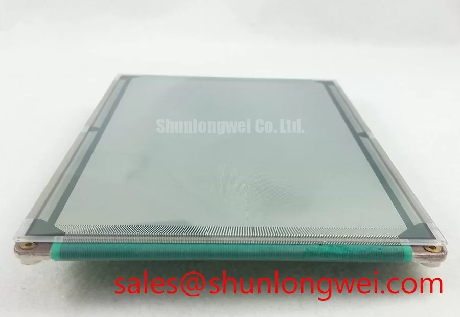
Do not make assumptions about chip on glass construction, tape automated bonding arrangement, or anisotropic conductive film materials for the EL640.400-CB1 without original manufacturing documentation. External inspection should focus on what can be reliably observed: connector alignment, cable latch condition, panel edge damage, display surface condition, mounting pressure, and uniformity under test patterns.
For replacement evaluation, compare the original panel label, mechanical envelope, cable direction, connector type, display mapping, power sequence, and optical requirements. Engineers considering another industrial display for a constrained retrofit can review NL192108JC18-03ND as a separate model, subject to full mechanical and electrical verification. For broader troubleshooting practices involving industrial panel integration, cable handling, and HMI environmental assessment, see Industrial Display & HMI Solutions.