

Content last revised on September 23, 2026
LTM10C209H Display Module Inspection and Verification
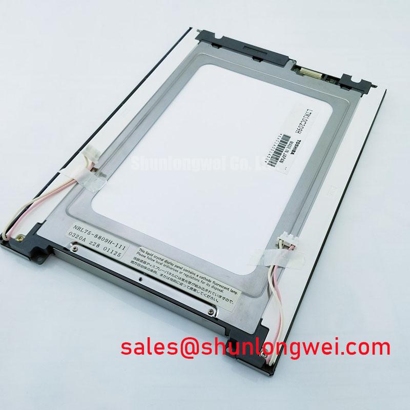
With power removed, first inspect the LTM10C209H module’s active surface, edge seals, frame, and flex or connector area under angled light before reconnecting it to the original HMI controller. This practical check can reveal pressure marks, contamination paths, loose retaining hardware, or moisture residue that may affect image uniformity or electrical connection after installation.
The LTM10C209H is identified as a TFT-LCD Display Module in the Industrial Grade LCD/HMI Panel category. The available official factory information identifies Toshiba / Samsung as the listed manufacturer attribution and confirms its status as Official Factory Spec Verified. No supply voltage, interface pinout, backlight technology, optical specification, mechanical drawing, operating-temperature range, or mounting torque value is confirmed in the provided factory specification. The system integrator should verify these items from the original panel documentation and the equipment-side harness before replacement.
| Parameter | Official Factory Specification |
|---|---|
| Product Model | LTM10C209H |
| Manufacturer Attribution | Toshiba / Samsung |
| Product Category | Industrial Grade LCD/HMI Panel |
| Module Type | TFT-LCD Display Module |
| Specification Status | Official Factory Spec Verified |
Flashlight Dark-Shadow Optical Diagnostic to Isolate Logic vs. Backlight Failure Modes
Before treating a dark display as a panel failure, technicians should separate image-generation behavior from illumination behavior. With the original controller energized only under the equipment’s approved service procedure, set the HMI to a stable diagnostic image when its software permits. A full red field, a full green field, and a full blue field provide a practical primary-color sequence for checking whether the screen responds consistently across its visible area. This is an Engineering Recommendation for bench diagnosis, not an official test procedure for the LTM10C209H.
When the display appears dark, use a flashlight at approximately a 45-degree angle across the front surface while viewing from several positions. A faint but recognizable image can indicate that video data and pixel addressing may still be present while the illumination path requires further investigation. No visible image does not automatically identify a panel-level defect. The condition can also be related to the host controller, cable seating, signal integrity, power sequencing, or an incompatible replacement assembly. Compare observations with a known-good signal path where available.
Thin lines, intermittent bands, color changes, or an image that alters when the chassis is touched should be documented without flexing the module. Localized visual defects may be associated with connector contact, mechanical loading, display glass damage, controller behavior, or other assembly-level conditions. Do not infer a chip-on-glass fracture solely from one screen symptom. Verify the input signal and supply behavior with appropriate instruments before removing the panel from the diagnosis chain.
The factory information supplied for LTM10C209H does not specify PWM dimming frequency, dimming duty-cycle behavior, or backlight-control logic. Values sometimes associated with other industrial display systems, including 200 Hz to 1 kHz dimming ranges, must not be assigned to this model without the original documentation. If the equipment uses brightness control, engineers should observe the actual control waveform and display response under normal and reduced brightness conditions, checking for visible flicker, acoustic noise, or unstable luminance.
Maintenance Note: Inspect cooling-air paths, enclosure gaskets, and mounting pressure points during scheduled service because dust accumulation, hardened seals, and uneven clamping can contribute to thermal stress, condensation exposure, and localized visual non-uniformity.
Verification of Any Dual-Channel CCFL High-Voltage Resonant Inverter and Ignition Path
The available official factory data confirms a TFT-LCD display module but does not identify its illumination technology or confirm the presence of CCFL lamps, a dual-channel inverter, LED strings, or an integrated backlight driver. A service engineer should therefore inspect the original equipment architecture rather than applying a generic backlight diagnosis sequence. Determine whether the display assembly receives a dedicated illumination connector, whether the HMI controller contains a separate driver board, and whether the equipment documentation identifies dedicated enable or brightness-control signals.
High-voltage ignition figures, lamp striking voltage, constant-current LED characteristics, dimming ratio, and lamp or LED lifetime data are not official specifications provided for the LTM10C209H. They should not be used as replacement acceptance criteria. If an external illumination driver is present, assess it as a separate subsystem and follow the driver manufacturer’s safety instructions. Measurement near energized high-voltage circuitry requires properly rated probes, insulated access methods, and the site’s lockout procedure.
Where the original equipment uses a digital video connection, the panel-side interface must be verified from the original documentation rather than inferred from the product category. TTL and LVDS use different signal conventions, connector assignments, voltage expectations, and timing requirements. Clock-jitter margin, data hold time, synchronization polarity, and power-on sequencing are host-system conditions unless expressly specified in the panel documentation. An apparently compatible connector shape is not evidence of electrical compatibility.
During controlled troubleshooting, begin with the original cable, the original controller, and a stable test image. Inspect connector retention, bent contacts, cable strain relief, and grounding continuity around the display enclosure. A display that changes behavior with vibration may indicate a connection or mechanical-support issue, but it should be evaluated against known-good hardware before an isolated cause is assigned. For broader maintenance practices involving industrial HMI environmental exposure and equipment-side verification, consult Industrial Display & HMI Solutions.
Thermal Interface and Edge-Support Assessment Along Narrow Display Boundaries
The LTM10C209H factory data supplied here does not specify an aluminum heat spreader, thermal-interface material, backlight power dissipation, or permitted edge-loading condition. Any decision to add thermal hardware must therefore be treated as a Design Consideration based on the complete equipment enclosure, original mechanical arrangement, and measured temperature behavior. A heat spreader that improves one local temperature condition can create a new stress path if it distorts the frame or concentrates fastening force.
For preventive maintenance, inspect whether the panel frame is supported evenly by the bezel and whether foam seals, gaskets, or spacers remain aligned. Uneven support can create local pressure on the front surface and may contribute to bright spots, dark areas, or mura-like non-uniformity. Do not use the display face as a clamping reference. Retain the original stack-up, spacer locations, and fastening sequence whenever equipment documentation defines them.
In AGV or forklift telematics installations, vibration, cabin temperature changes, and airborne contamination are system-level concerns rather than confirmed product ratings for this module. When assessing suitability, technicians should verify the display’s physical fit, enclosure sealing, harness strain relief, and controller interface against the original installation. A replacement panel should not be accepted solely because it powers on at the bench; the assembled equipment must also be checked for stable operation after reinstallation.
Condensation control deserves particular attention where a vehicle moves between cold storage, loading areas, and warmer warehouse zones. The enclosure should be inspected for damaged perimeter seals, blocked breathing paths where applicable, and water entry routes around cable penetrations. Allow the equipment to reach a safe service condition under the facility’s maintenance rules before applying power after suspected moisture exposure. No humidity tolerance or condensation rating is stated in the available official specification for LTM10C209H.
Viewing-Angle, Surface Condition, and Multi-Angle Console Verification
The supplied official specification identifies the LTM10C209H as a TFT-LCD module but does not confirm TN, IPS, MVA, Super-IPS, viewing-angle values, contrast ratio, surface treatment, or anti-glare coating. The commonly referenced 85/85/85/85 viewing-angle format must not be presented as an official characteristic of this model without the relevant factory optical datasheet.
For a field replacement evaluation, display a stable text page, grayscale page, and color image through the original HMI controller. Observe the panel from the operator’s expected standing or seated positions, then from off-axis positions likely to occur in the equipment installation. Note any contrast inversion, color shift, reflection, uneven brightness, or loss of readability. These observations support system-level acceptance but do not establish the underlying panel technology.
Surface cleaning should be conservative. Use only procedures approved by the equipment manufacturer or original panel documentation, since unverified solvents, abrasive materials, and excessive liquid can affect surface coatings, bezel seals, or edge interfaces. If the front surface is exposed to high ambient illumination, assess glare using the actual enclosure window and operator viewing position rather than assuming an anti-glare finish.
For rugged telematics displays on automated guided vehicles and forklifts, procurement and maintenance teams should confirm the exact original interface, mechanical envelope, front-surface condition, mounting arrangement, and equipment-side electrical behavior before integration. The available verified information supports identification of the LTM10C209H as a Toshiba / Samsung TFT-LCD Display Module; all unlisted electrical, optical, thermal, and mechanical requirements remain subject to verification from the original equipment documentation.