

Content last revised on October 11, 2026
Solid-State WLED Constant-Current Driving, PWM Dimming & Flicker Suppression
Inspect the bezel contact surfaces, cable seating, and unpowered connector condition before reconnecting the M185XTN01-2 to an existing display controller. Record whether the original fault changes with brightness, cabinet temperature, or mechanical fastening; these observations help separate illumination, signal-path, and mounting problems without treating one symptom as a definitive diagnosis.
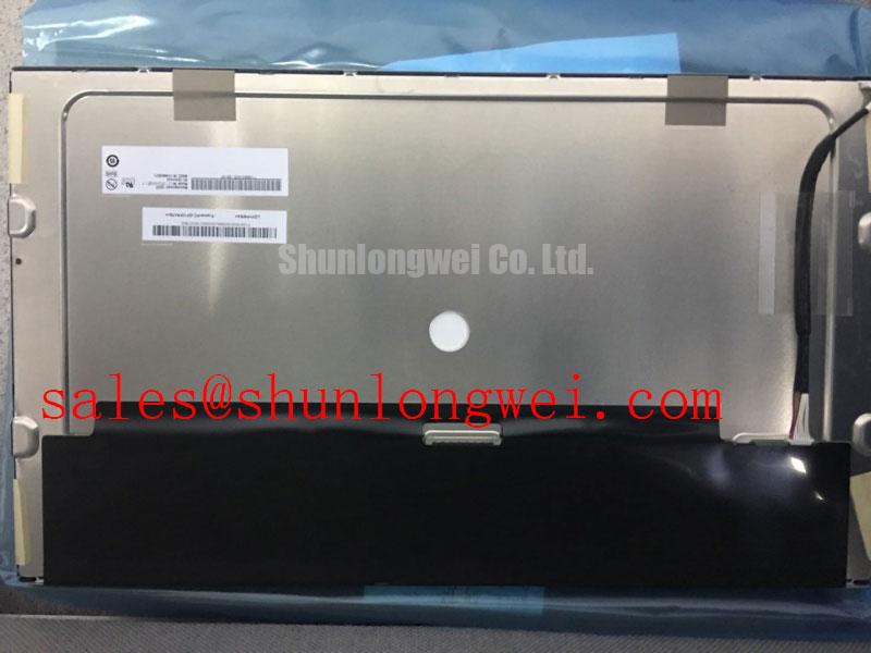
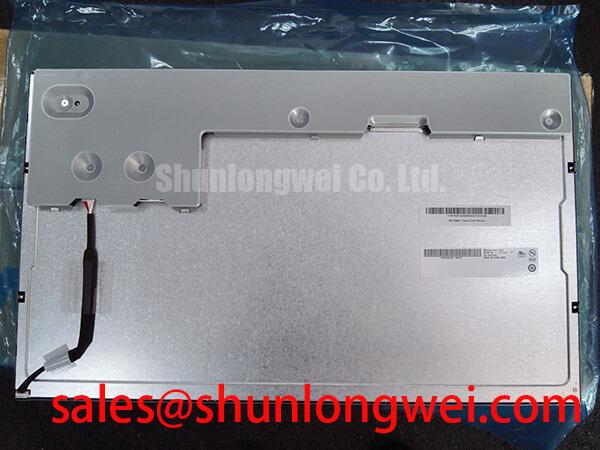
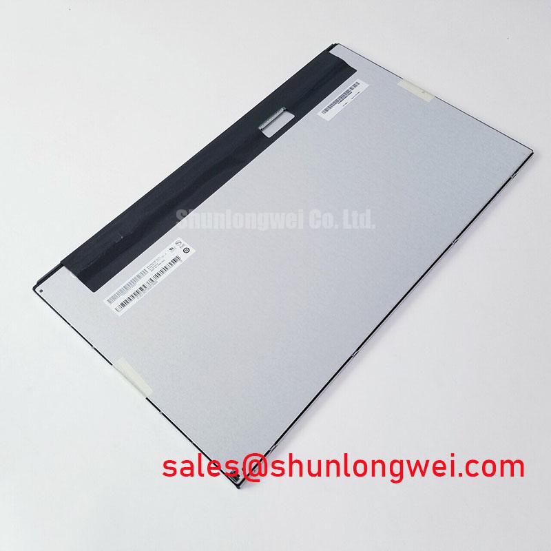
The product baseline identifies a TFT-LCD active-matrix color display module from AU Optronics (AUO), considered here for industrial LCD/HMI applications. For the M185XTN01-2, replacement assessment should follow the complete panel label and revision rather than the model family alone. The dimming methods and interface terms in the headings below describe evaluation topics, not verified electrical ratings or installed features of this module.
Observe the display at several commanded brightness settings while monitoring the host backlight control and driver output. As a Design Consideration, a constant-current LED driver regulates illumination current, while PWM control changes the illuminated portion of each cycle. Stable operation depends on the relationship between the controller command, driver response, backlight load, and power supply; a dimming label alone does not establish flicker performance.
Keep the illumination diagnosis separate from the image-data diagnosis. A changing overall brightness level with otherwise stable text suggests a different investigation from shifting pixels or intermittent lines. Compare the brightness-control waveform with the visible disturbance, using measurement equipment appropriate to the driver circuit. Camera banding can also depend on exposure settings, so it should not be the sole evidence of a display fault.
No model-specific dimming ratio is established here. Nor should a cold-ignition test intended for a different backlight architecture be transferred to this panel. Identify the installed backlight assembly and its driver requirements through the matching circuit documentation before selecting instruments or applying test power. This avoids importing unrelated ignition voltages, current settings, or dimming limits into a replacement assessment.
For thermal evaluation, compare brightness uniformity after the assembly reaches a stable operating condition. Restricted cabinet airflow or heat from neighboring electronics can influence the display assembly’s temperature distribution. Local dimming, color changes, and edge shadows warrant inspection of both the illumination path and surrounding installation. Do not infer a particular light-guide material or internal construction from the appearance of the defect.
Brightness retention and MTBF describe different reliability measures: one concerns optical output over time, while the other concerns failures under stated conditions. Neither establishes a service-life guarantee for this model. Maintenance records are more useful when they document operating conditions, brightness settings, and repeatable measurements than when they assign an unsupported lifetime to an individual panel.
Industrial Bezel Mechanical Envelope Tolerances & Mounting Screw Torque Optimization
Seat the panel against its intended supports without using the bezel screws to pull a misaligned assembly into position. As a Design Consideration, uneven clamping can distort an LCD assembly and change its visible uniformity. Check bracket alignment, gasket placement, cable clearance, and contact surfaces before adjusting fastening loads.
A dark-field image can help reveal mounting-related nonuniformity, but it does not identify the cause by itself. Compare the image with the assembly supported correctly and again after fastening according to the enclosure drawing. If the pattern changes, inspect the mechanical load path rather than increasing screw pressure. Fastener size, engagement depth, permissible torque, and tightening sequence belong to the actual panel-and-enclosure assembly; a generic torque range is not a model-specific limit.
Gasket contact should be continuous where the enclosure design requires sealing, without forcing the bezel against unsupported display surfaces. Inspect displaced corners, hardened sections, and debris trapped beneath the seal. The surrounding enclosure determines environmental protection; the panel category alone does not establish a dust or water ingress rating.
Maintenance Note: Periodically inspect cabinet airflow paths and bezel gasket condition before adjusting brightness to compensate for a dim or uneven image.
For replacement planning, the following comparison separates supplied identity information from the assembly details that determine interchangeability. The linked model is a comparison candidate, not an established direct replacement.
| Assessment item | M185XTN01-2 | M185XW01 V4 |
|---|---|---|
| Product identity | TFT-LCD active-matrix color display module | Separate model requiring its own documentation |
| Manufacturer designation | AU Optronics (AUO); verify the complete panel label | Consult matching datasheet and panel label |
| Resolution and mechanical envelope | Consult matching datasheet | Compare active area, outline, mounting features, and clearances |
| Electrical compatibility | Consult matching datasheet | Compare connector assignment, supply requirements, and timing |
| Replacement status | Reference model for this assessment | Not established as interchangeable |
When comparing M185XW01 V4, include cable exit direction and bezel aperture alignment alongside electrical compatibility. Evaluation for a factory-automation machine-tool HMI operator terminal should also account for the installed viewing position and protective window. Ambient reflections can reduce usable contrast, but sunlight performance and anti-glare treatment require their own specified test conditions.
After moving a cold assembly into a warmer environment, allow moisture conditions to stabilize before energizing it. Check for condensation on the display window and connectors rather than assuming that an acceptable air temperature also means dry surfaces.
Differential LVDS Timing, Pixel Clock & Skew Compensation
Match the controller connector assignment to the exact panel revision before adapting an existing harness. As a Design Consideration, connector position count does not establish pin compatibility, signal mapping, or supply requirements. A mechanically mating connector can still connect the wrong functions, making an end-to-end harness comparison essential.
For an LVDS integration, compare data-lane assignments, clock connections, grounds, and any control signals in the controller and panel drawings. Confirm the specified pixel format and mapping before interpreting incorrect colors or a divided image. Mapping, timing, and signal integrity can produce overlapping symptoms, so troubleshooting should use test patterns and measured behavior rather than assigning each visual artifact to one cause.
Maintain consistent differential-pair geometry through the host routing, connector transition, and cable. Impedance discontinuities and unequal path delays can reduce receiver margin, particularly where a harness has been extended or repaired. The appropriate impedance target and skew allowance come from the interface implementation and timing requirements; they are not established by connector position count alone.
Capture panel power, data activity, and illumination control during startup and shutdown. Compare their order and transition behavior with the matching timing specification. A steady supply reading cannot reveal a startup dip or an incorrect sequence, and a successful warm restart does not prove that cold startup is correct. Preserve the intended sequence when changing the controller or harness.
For grayscale checks, use repeatable ramps and neutral patches with the host image settings held constant. T-CON operation, grayscale references, gamma configuration, and source-image processing can all affect tonal behavior. Where documented test points exist, measurements should follow the service procedure; changing gamma settings to hide an intermittent fault can obscure the underlying problem.
Evaluate viewing-angle color changes at the installed operator position. Do not assume IPS or MVA construction for M185XTN01-2 from a preferred application. The AU Optronics website provides manufacturer context for display technologies, but model-specific optical behavior must remain tied to the matching panel specification.
Industrial EMI Noise Immunity, Chassis Shielding Continuity & Common-Mode Ferrite Chokes
Correlate pixel disturbances with nearby switching activity before changing the display harness or adding suppression components. As a Design Consideration, conducted disturbances, coupling into the cable, and unstable power can create similar visible effects. Compare the same image under repeatable equipment states while observing the relevant supply and interface signals.
Inspect the intended shield path from the cable termination to the chassis connection. Loose contacts, paint beneath bonding surfaces, or an altered harness route can change high-frequency behavior. Where the equipment design specifies a circumferential shield termination, retain that arrangement rather than replacing it with an improvised connection. Shield treatment must follow the complete equipment grounding design.
A common-mode ferrite is an optional system-level measure, not a stated accessory of this panel. Selection should follow the measured disturbance and cable arrangement. Evaluate any change against both image stability and interface operation, because suppression that alters the signal path can introduce a different problem. Keep the display cable separated from noisy power wiring where the enclosure layout permits.
For longer-term inspection methods, The Ultimate Guide to Industrial TFT LCD Technology offers broader background without replacing model-specific limits. Record brightness comparisons under consistent settings and thermal conditions, and distinguish gradual optical change from intermittent electrical disturbance. Any brightness-decay assessment requires defined conditions; it should not be converted into an unsupported MTBF claim.
After correcting a shield connection or cable route, repeat the operating condition that previously produced the disturbance. Check image stability, power behavior, and enclosure reassembly together. Component-level checks support this diagnosis, while EMC compliance remains a property of the completed equipment evaluated under its applicable test requirements.