

Content last revised on September 22, 2026
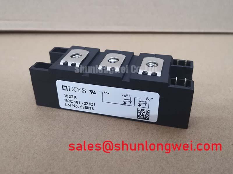
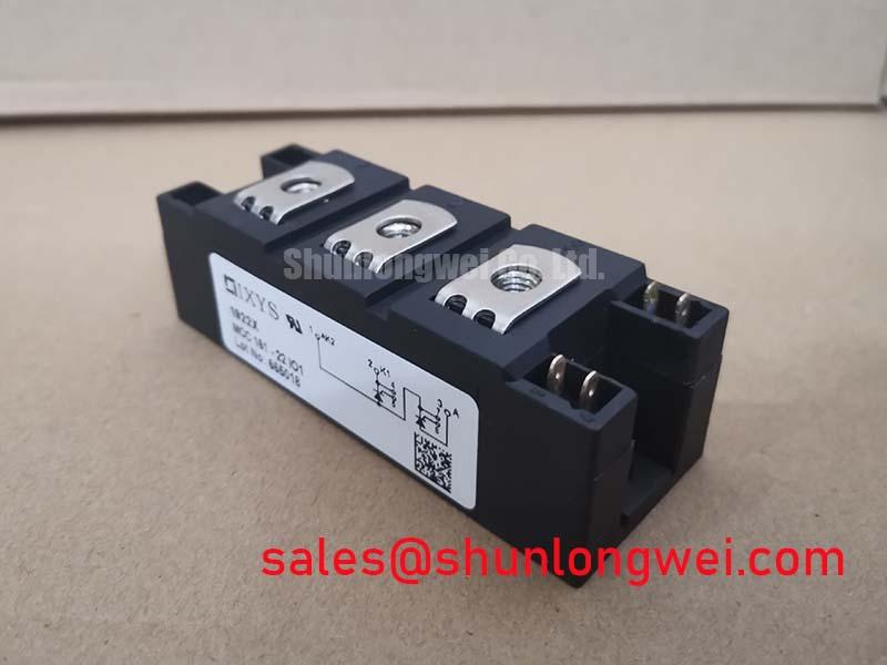
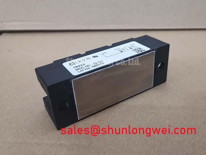
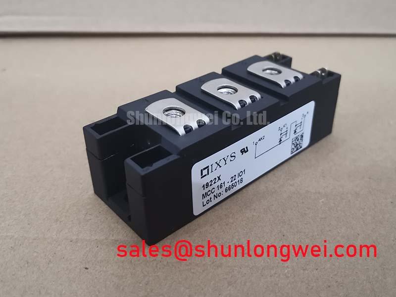
MCC161-22IO1 IXYS 2200V 161A Dual Thyristor Module
Begin commissioning by isolating the equipment, checking the module marking against the service record, and confirming the electrical boundary of 2200 V and 161 A before connecting any test circuit. The IXYS MCC161-22IO1 is a Dual Thyristor Module in a module package. These voltage and current values are official product specifications supplied for this product page; they should not be treated as a complete system operating limit without reviewing the original circuit, cooling arrangement, protection network, and operating duty.
| Parameter | Specification | Classification |
|---|---|---|
| Manufacturer | IXYS | Product identification |
| Model | MCC161-22IO1 | Product identification |
| Product category | Dual Thyristor Module | Product classification |
| Rated voltage | 2200 V | Official specification |
| Rated current | 161 A | Official specification |
| Package | Module | Official physical specification |
For maintenance teams evaluating a high voltage three phase motor solid state soft starter, the rating check is only the first gate. The integrator should confirm the original terminal arrangement, gate drive requirements, fuse coordination data, cooling method, and switching duty from the applicable IXYS documentation. The product information available here does not establish a particular mounting torque, gate current, thermal resistance, surge current, reverse recovery specification, fuse I2t value, or insulation rating, so those values should be verified from the relevant datasheet before replacement or commissioning.
Field Diagnostics and Commissioning: Thermal Interface Material Spreading across MCC161-22IO1 Topologies
Start a thermal inspection with the equipment fully de-energized and the DC link discharged according to the machine service procedure. Check the module body, baseplate area, heat sink surface, terminals, and surrounding insulation for contamination, corrosion, distortion, or signs of uneven contact. A visual check cannot establish thermal performance by itself, but it can identify conditions that justify removing the module for closer inspection.
The MCC161-22IO1 is specified as a 2200 V, 161 A dual thyristor module. Those figures identify the electrical class of the device; they do not define the permissible continuous current under every ambient temperature or heat sink condition. When the module is installed in a soft starter, maintenance personnel should compare measured case or heat sink temperature with the equipment manufacturer’s limits and operating records. A rising temperature trend at a similar motor load may justify checking airflow, heat sink cleanliness, interface material condition, terminal tightness, and phase balance.
Thermal interface material should cover the intended contact area without introducing foreign particles or a thick uneven layer. The module should sit flat against the heat sink without forced distortion. Mounting hardware, washer arrangement, and tightening sequence should follow the applicable IXYS mechanical instructions or the equipment manufacturer’s service specification. Because a product specific torque value is not included in the supplied data, no fixed torque should be assigned to this model here.
After assembly, inspect the contact boundary and verify that the heat sink is not rocking against the module base. Check power terminals for secure mechanical connection and inspect gate and auxiliary wiring for strain, damaged insulation, or incorrect routing. Fuse coordination must be checked against the manufacturer’s published I2t and surge data for the actual protection device. Those values are not provided in the product information above and should not be inferred from the 161 A rating.
Maintenance Note: Schedule periodic heat sink cleaning and monitor contact temperature trends while checking the cooling airflow for obstruction, dust loading, and moisture or condensation exposure.
For procurement teams comparing the physical role of high current semiconductor modules, SKKT91/08D may be reviewed as a separate reference product, but electrical, mechanical, gate, and thermal compatibility must be confirmed independently rather than assumed from package appearance or current class.
Transient Dynamics and Electrical Design: Reverse Recovery Charge Temperature Coefficient on MCC161-22IO1
In a soft starter, the thyristor pair operates during controlled AC conduction, and the commutation environment is determined by the motor, line impedance, transformer arrangement, wiring, suppression network, and control timing. During bench evaluation, engineers should observe the semiconductor voltage and current with appropriately rated, isolated measurement equipment. A waveform that appears clean at low power may change when motor current, temperature, or line conditions change.
The supplied product parameters confirm the voltage class of 2200 V and current class of 161 A, but they do not provide reverse recovery charge, reverse recovery time, peak reverse recovery current, critical rate of rise of off-state voltage, or critical rate of rise of on-state current. These are important values for commutation and protection design, yet assigning numerical values without the applicable datasheet would create an unsupported specification.
As a design consideration, the commutation loop should be kept compact and its parasitic inductance controlled to limit voltage overshoot during current transfer. The protection network should be selected from measured switching waveforms and verified against the actual line voltage, load characteristics, and fault-clearing arrangement. An RC snubber, MOV network, or other suppression method should not be treated as interchangeable without checking leakage current, energy absorption, repetitive duty, and coordination with the upstream protective device.
Temperature affects semiconductor switching behavior and the surrounding thermal conditions. Engineers should therefore record waveform and temperature results at representative cold, stabilized, and high-load conditions rather than relying on a single room-temperature test. If the measured commutation waveform shows unexpected ringing, first compare the probe connection, grounding method, wiring layout, and known-good phase path before assigning the observation to the thyristor module.
The relationship between auxiliary power conversion, commutation control, and switching transients depends on the complete topology. For background reading on converter arrangements, the buck boost converter reference provides general topology context, but it is not a substitute for the IXYS application data applicable to this module or soft starter.
Gate drive wiring should be routed according to the original equipment design, with control and power conductors separated where practical. If a negative off bias is being considered, the drive designer should verify gate-cathode limits, isolation, turn-off behavior, common-mode transients, and the control supply sequence from the device documentation. The guide Evolution of Negative Off-Bias Gate Drive Circuits can support that engineering review without establishing a mandatory setting for MCC161-22IO1.
Benchtop Waveform Tuning: Mitigating Stress through Dynamic Firing Delay Angle Adjustment on MCC161-22IO1
Before changing firing control, document the original soft starter settings and verify that the test motor, line source, bypass arrangement, and protection devices match the intended service condition. A thyristor module rated at 2200 V and 161 A may be suitable for evaluation in a high voltage motor starter, but system suitability depends on conduction angle, duty cycle, cooling, fault protection, and the motor’s starting characteristics.
Adjusting the firing delay changes the interval during which each thyristor conducts. That change influences motor terminal voltage, input current shape, displacement power factor, reactive power demand, acceleration behavior, and heat generation. The practical target is not a particular angle applied universally; it is stable motor acceleration with measured current, voltage, temperature, and mechanical response remaining within the equipment design limits.
When tuning on the bench, increase or decrease the delay in controlled increments defined by the system engineer and allow the measured waveform to stabilize before making another adjustment. Record phase current balance, line-to-line voltage, motor acceleration, module case temperature, and any abnormal acoustic or mechanical response. If one phase differs from the others, inspect the gate command path, terminal connections, current measurement channel, and upstream line condition before concluding that the module itself is responsible.
Firing control should also be reviewed against the bypass transition. A soft starter may experience a different electrical environment when the bypass contactor closes, and the control system should verify that thyristor triggering, contactor timing, and load transfer occur in the intended sequence. The available product information does not specify a firing-angle operating range, gate pulse width, gate current, or bypass timing for MCC161-22IO1.
For installations exposed to high altitude, severe temperature variation, condensation, or electrical transients, the system designer should obtain the relevant derating and environmental information from the manufacturer’s documentation. No cosmic-ray single-event burnout rate, FIT value, altitude limit, service life, or safety certification should be assumed from the 2200 V rating alone. These subjects require a documented device and system qualification basis.
Assembly Integrity and Layout Architecture: Snubber and Saturable Reactor Evaluation for MCC161-22IO1
Inspect the physical layout before energizing a replacement module. High-current paths should be short and mechanically supported, while gate wiring should be protected from avoidable coupling with rapidly changing power conductors. The heat sink, module base, bus connections, fuse, MOV, snubber, and grounding arrangement should be assessed as one assembly because a protection component can alter the stress seen by the thyristor during normal switching and fault conditions.
RC snubber selection is a system design task. The resistor and capacitor must be evaluated for voltage rating, pulse energy, repetitive dissipation, tolerance, temperature behavior, and physical placement. The network should be validated with measured voltage waveforms at the module terminals. The supplied MCC161-22IO1 information does not specify an approved snubber resistance, capacitance, capacitor technology, or damping arrangement, so these values must come from the applicable application design rather than from the module’s current and voltage ratings alone.
An MOV can provide a clamp path for abnormal overvoltage, but its rating and energy capability must coordinate with the line voltage, transformer impedance, fuse behavior, repetition rate, and expected surge environment. The engineer should verify that the MOV does not conduct excessively during normal operation and that its failure mode is addressed by the surrounding protection. An MOV is not a replacement for correct commutation layout or properly coordinated semiconductor fusing.
A saturable reactor may be considered where the system requires control of current rise during a specific transient. Its core behavior, saturation point, temperature rise, insulation system, and placement must be tested under the actual starting and fault conditions. The module’s official 161 A current rating does not define the reactor rating, permissible inrush profile, or short-circuit withstand of the assembled soft starter.
Fuse coordination should use the manufacturer’s published semiconductor fuse tables and the measured prospective fault conditions. Confirm the fuse voltage rating, clearing behavior, I2t relationship, installation geometry, and replacement specification. Since no fuse I2t table is included in the supplied product data, it would be unsafe to nominate a fuse solely from the MCC161-22IO1 current figure.
Final commissioning should include a visual inspection after the first controlled run, a check for abnormal heating at terminals and interfaces, and a review of logged phase currents. Any protective network modification should be retested for conducted and radiated disturbance within the complete equipment, because a semiconductor module cannot independently claim compliance with an entire machine’s EMC or safety requirements.