


Content last revised on November 11, 2026
MD200S16M3 Incoming Inspection and Safe Bench Checks
- Isolate the equipment, verify stored energy is discharged, and match the terminal markings to the circuit drawing before connecting a meter.
- Record cold forward and reverse diode-mode readings with external parallel paths disconnected, using consistent probe polarity and module temperature.
- Inspect the mounting surface, terminal seating, and thermal interface for contamination, uneven contact, or mechanical distortion.
- Check the equipment’s insulation-test procedure before applying any voltage between terminals and the mounting surface.
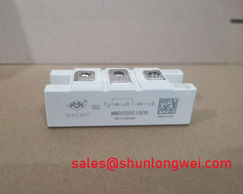
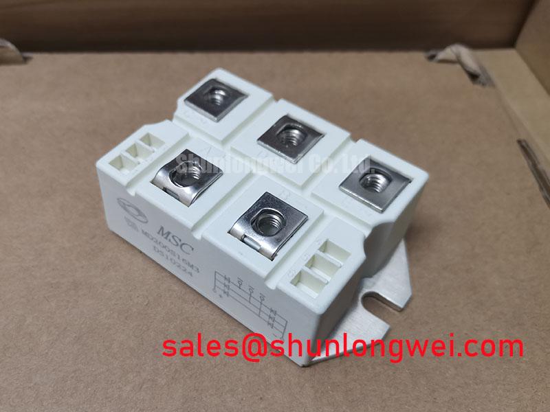
The MD200S16M3 from MacMic is a Diode Module with the specified configuration Thyristor / Diode Module. Incoming inspection should establish terminal identity before interpreting static measurements; the configuration description alone does not establish the internal connection diagram or gate-terminal assignment.
| Specification | Product rating or identification |
|---|---|
| Manufacturer | MacMic |
| Part Number | MD200S16M3 |
| Product Category | Diode Module |
| Repetitive Peak Reverse Voltage (VRRM) | 1600.0 V |
| Average On-State Current (IT(AV)) | 200.0 A |
| Package | Module |
| Configuration / Topology | Thyristor / Diode Module |
| Additional acceptance limits | Consult Datasheet: terminal diagram, current-rating conditions, thermal resistance, surge withstand, gate characteristics where applicable, mounting torque, and insulation test conditions. |
💡 Bench Tip: After verifying discharge, use ESD-controlled handling and compare cold readings with a known-good reference under the same meter settings rather than treating one forward-voltage reading as an acceptance limit.
MD200S16M3 Circuit Protection & Reliability: Assessing Junction-to-Heatsink Heat Dissipation
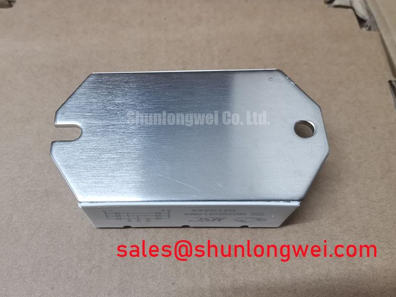
Check mounting-face flatness and thermal-interface coverage before judging heat dissipation from heatsink temperature. As a Design Consideration, uneven contact pressure can increase interface resistance even when the cooling assembly appears correctly sized. Clean the mating surfaces, inspect the spread pattern during a controlled assembly check, and apply the documented fastening sequence without distorting the housing.
Separate junction-to-case thermal resistance from case-to-heatsink interface resistance in the thermal assessment. Do not assume a copper baseplate or assign a material-specific thermal model without the mechanical drawing. Where transient thermal impedance, Zth, is specified, an Engineering Recommendation is to evaluate pulse duration and repetition against that curve rather than applying steady-state thermal resistance to every load event.
The 200.0 A average on-state rating requires its associated waveform and cooling conditions for interpretation. An Engineering Recommendation is to compare the protective fuse’s total clearing I²t with the module’s permissible surge conditions and the prospective fault current. Terminal tightening torque and mounting torque should remain separate entries in the assembly record; neither should be inferred from appearance.
For packaging background, the general discussion of thermal shock explains why rapid temperature changes stress assemblies. It does not establish MIL-STD-202 qualification or a thermal-cycling rating for this module.
Benchtop Waveform Tuning: Mitigating Stress via Surge Energy Dissipation and Voltage Clamping on MD200S16M3
Measure the voltage at the module terminals when assessing an upstream MOV or RC suppression network. As a Design Consideration, wiring inductance between the suppressor and semiconductor can leave a terminal overshoot that is absent at the protection device itself. Use appropriately rated differential measurement equipment and a controlled test arrangement.
The 1600.0 V repetitive peak reverse rating is a semiconductor blocking limit, not an insulation-test voltage or an equipment surge-immunity rating. IEC 61000-4-5 is the relevant surge-immunity reference. The applicable equipment standard determines test conditions; the module rating does not establish system compliance.
When integrating protection, designers should coordinate MOV continuous operating voltage, clamping behavior, pulse-energy capability, and upstream fault protection with the actual supply. RC network evaluation should include capacitor pulse duty and resistor heating. These are Design Considerations, with component values determined by measured circuit behavior rather than a universal recipe.
The system-level article Power, Safety, Efficiency provides complementary power-conversion context, not MD200S16M3 acceptance criteria. For insulation assessment, inspect terminal creepage paths and clearances within the assembled equipment, considering contamination, connected conductors, and the approved test procedure.
MD200S16M3 Thermal-Electrical Optimization: Turn-On Current Rise Limiting
Check the connection drawing for any controlled junction and its gate return before evaluating turn-on behavior. As an Engineering Recommendation, use diode-mode measurements to compare identified paths in both polarities; investigate unexpected readings after excluding parallel components, probe-contact problems, and temperature differences. A handheld meter cannot establish reverse-blocking performance at the rated voltage.
For a confirmed thyristor path, assess gate trigger current and voltage against the specified test conditions. A gate-to-cathode resistance check is only a preliminary screen, not proof of triggering or latching performance. As a Design Consideration, pulse-train triggering should be evaluated against permitted gate power, pulse duration, and the load-current buildup.
Snubbers primarily influence voltage transients, while series inductive elements can influence current rise. Their interaction needs system testing: a saturable reactor changes behavior with operating state, and a snubber can introduce additional discharge current. These Design Considerations require simultaneous voltage and current observation rather than adjustments based solely on waveform appearance. Shindengen’s power semiconductor resources offer broader device background, not interchangeable MacMic specifications.
For replacement assessment, compare MSD200-16 documentation by topology, terminal assignment, mounting dimensions, and electrical test conditions rather than model-name similarity. When evaluating MD200S16M3 for a medium-frequency induction melting or hardening furnace power supply, designers should verify rectifier-stage compatibility, cooling, protection coordination, and any required gate-drive interface before approving installation.