
Content last revised on October 2, 2026
Preventing Spurious Faults: Non-Repetitive Surge Current Guidelines for MDS250A1600V
| Manufacturer | SanRex (Sansha Electric) |
| Model | MDS250A1600V |
| Category | Bridge Rectifier Module |
| Topology | Three Phase Diode Bridge Rectifier |
| Rated Voltage | 1600 V |
| Rated Current | 250 A |
| Package | Three Phase Rectifier Case |
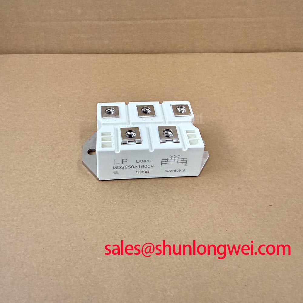
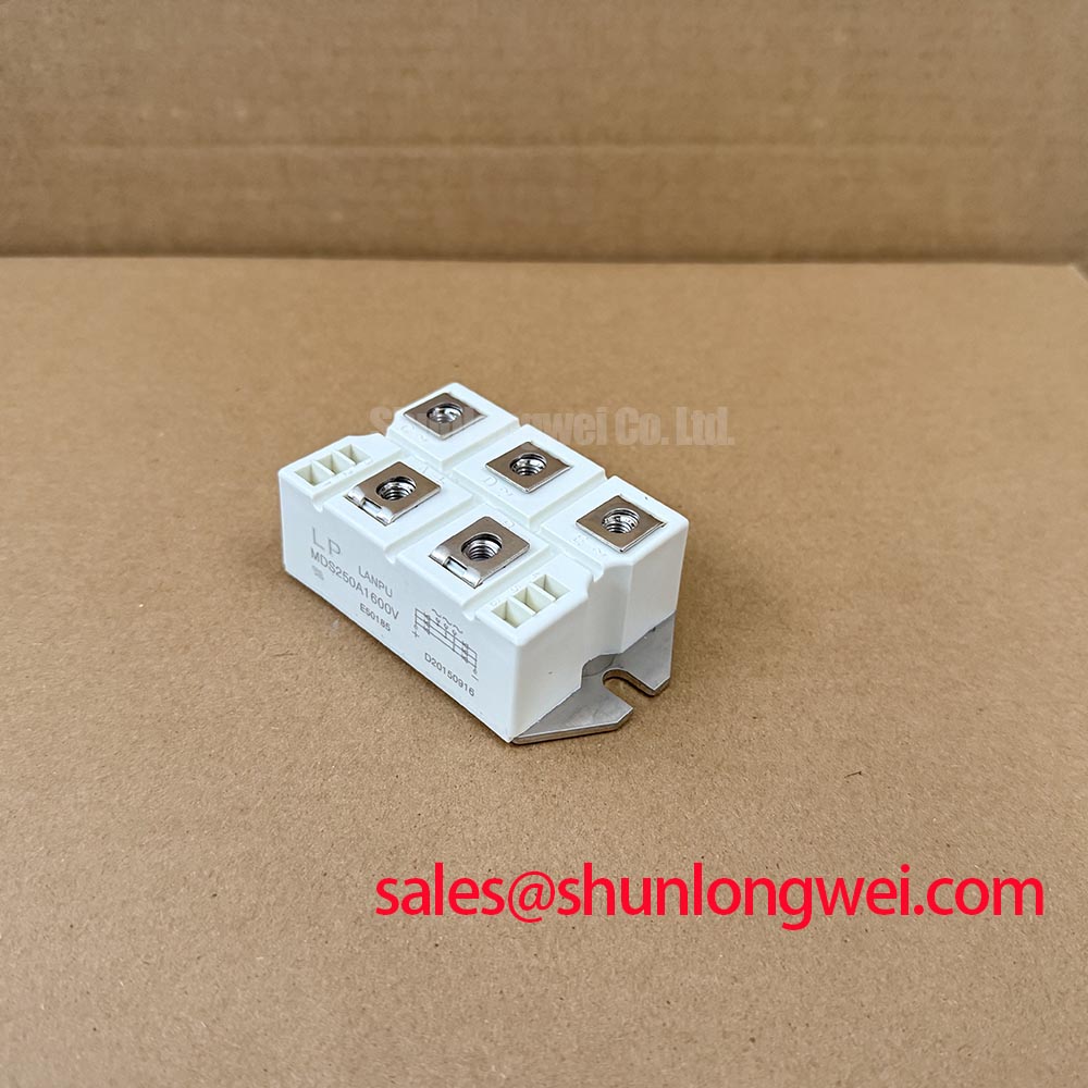
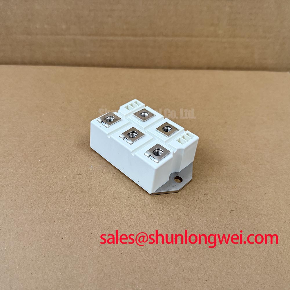
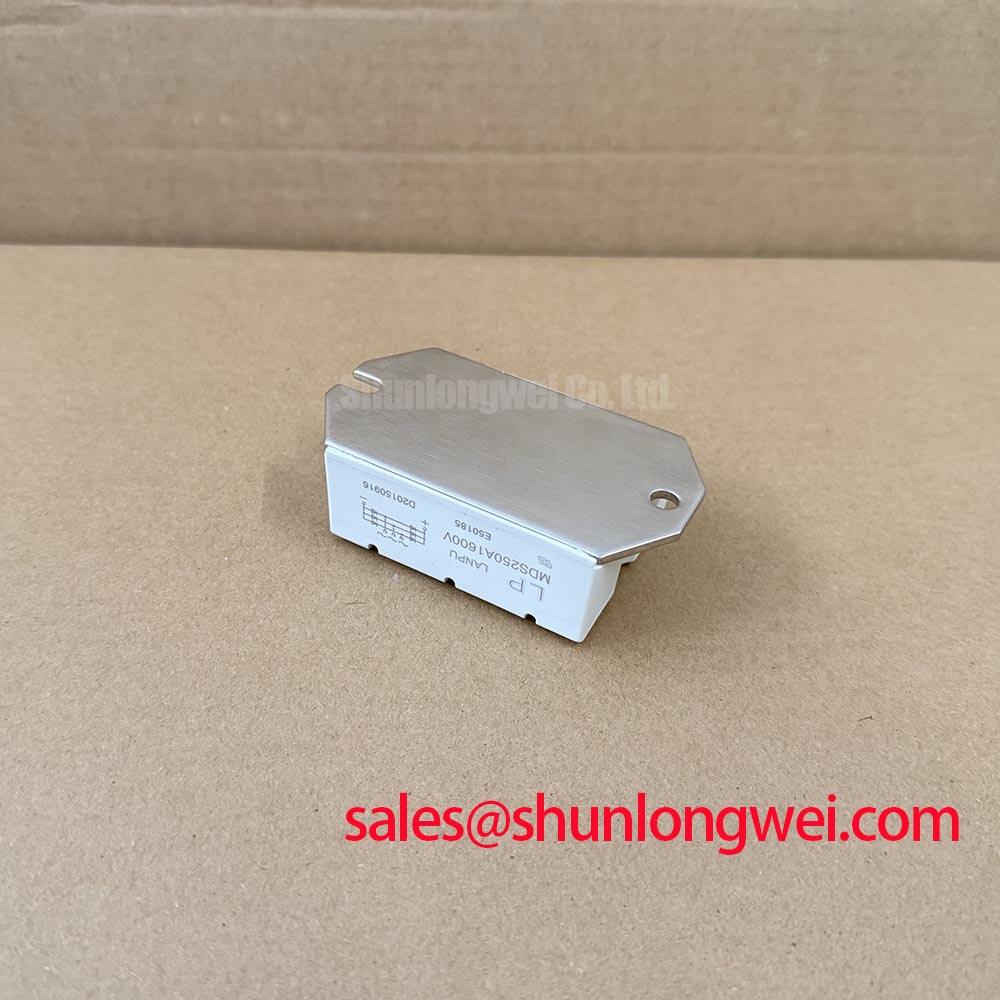
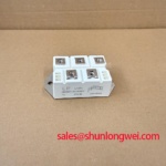
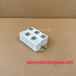
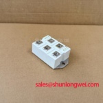
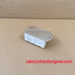
Measure the phase to phase and phase to DC terminal paths with the equipment isolated, then compare the readings with a known good rectifier and inspect every terminal for heat discoloration, looseness, or surface contamination. The MDS250A1600V is a 1600 V, 250 A SanRex three phase diode bridge rectifier in a three phase rectifier case. These are the confirmed product ratings; they do not by themselves define the permissible non-repetitive surge current or the associated junction temperature limit.
For a failed unit in a high voltage three phase motor solid state soft starter, record the incoming line condition, DC bus behavior, fuse condition, and the timing of the fault. The non-repetitive surge current value, pulse duration, test waveform, and repetition conditions must be taken from the applicable SanRex documentation before judging a short duration overload. A fuse I2t coordination review is also required because a fuse can interrupt a severe fault without preventing semiconductor damage during the first current pulse.
Use the manufacturer’s specified mounting hardware and torque procedure for the actual case. Do not substitute a generic torque value for an undocumented MDS250A1600V installation requirement. Keep busbar faces flat and clean, support heavy conductors independently, and verify that terminal pressure remains stable after thermal cycling. The MDS1000A1600V is a related higher current SanRex device that may be evaluated where the original circuit documentation confirms electrical and mechanical compatibility.
Assembly Integrity and Layout Architecture: Implementing Turn On Current Rise Limiting
Inspect the rectifier terminals, busbar joints, and protective network for localized heating or carbon tracking immediately after a controlled commissioning test. The MDS250A1600V is a diode bridge rectifier, so it does not provide the gate controlled turn on function of a thyristor bridge. An RC snubber may help manage voltage transients, while a series reactor or another suitable network may limit current rise. Component values must be selected from the measured line impedance, switching arrangement, surge requirement, and verified semiconductor limits.
This distinction matters when the module is evaluated inside a soft starter. The rectifier can serve a front end or DC link function where the topology supports it, while phase angle control normally belongs to a separate controlled semiconductor stage. Designers should verify commutation paths, reverse voltage exposure, line frequency behavior, and protective coordination during oscilloscope testing rather than treating the 250 A marking as a complete dynamic current specification.
Minimize high current loop area and keep protective components physically close to the conduction path to reduce unwanted inductive overshoot. Any calculated snubber or reactor selection remains an Engineering Recommendation until the assembled system is tested under its actual voltage, current, and fault conditions. The MDS300A1600V may be reviewed as a related rectifier stage when the required current rating, package arrangement, and thermal interface are confirmed independently.
Field Diagnostics and Commissioning: IEC 61000-4-5 Industrial Surge Immunity
Capture the line side surge protection condition, DC bus rise, and rectifier terminal waveform during commissioning with probes rated for the circuit voltage and bandwidth. IEC 61000-4-5 testing applies to the equipment and its protection architecture; the MDS250A1600V itself should not be described as independently EMC certified. MOV selection, upstream fusing, series impedance, and RC suppression must be coordinated with the supply system and the equipment test level.
Check whether an MOV has experienced repeated thermal stress, leakage increase, cracking, or disconnection, and inspect the surrounding wiring for evidence of surge current. Use the applicable SanRex electrical limits when assessing the rectifier’s reverse voltage and current exposure. The official product data supplied for this listing confirms 1600 V voltage and 250 A current ratings, but it does not establish a universal IEC 61000-4-5 withstand level or a fixed MOV rating.
Protection enclosure selection is a system decision based on moisture, dust, access, and cooling requirements. The NEMA enclosure type reference provides useful terminology for industrial panel protection. ESD handling also requires a controlled work method; technicians should review the relevant ESD protection models before removing or installing the module.
Field Diagnostics and Commissioning: Three Phase Back to Back Thyristor Voltage in MDS250A1600V Topologies
Verify the semiconductor topology from the schematic before applying phase angle control, because the MDS250A1600V is identified as a three phase diode bridge rather than a back to back thyristor assembly. A diode bridge cannot independently control motor voltage angle or reduce locked rotor current from a stated multiple to another fixed multiple. Those functions require a compatible controlled power stage, gate drive, bypass arrangement, and motor protection system.
For a high voltage three phase motor solid state soft starter, compare the incoming line waveform, controlled phase waveform, bypass contactor timing, and motor current with the equipment manufacturer’s commissioning limits. Check whether the rectifier is positioned as an uncontrolled front end, a charging path, or another DC link element. The system engineer must verify insulation coordination, reverse voltage stress, fault clearing time, and thermal performance across the complete assembly.
Monitor heatsink cleanliness, airflow, interface condition, and terminal temperature during scheduled maintenance. Maintenance Note: Isolate power before disconnecting the module, and periodically verify contact temperature and cooling airflow under representative load.
For thermal design review, the transient thermal impedance network and pulse junction temperature margin should be taken from the applicable device documentation and then tested against the real mounting interface. The technical discussion of insulated substrates and double sided cooling in The Advanced Thermal Management Revolution can support broader thermal architecture work, but it does not replace the MDS250A1600V manufacturer’s device limits.