

Content last revised on October 1, 2026
Preventing Thermal Interface Faults in MDS300A1600V
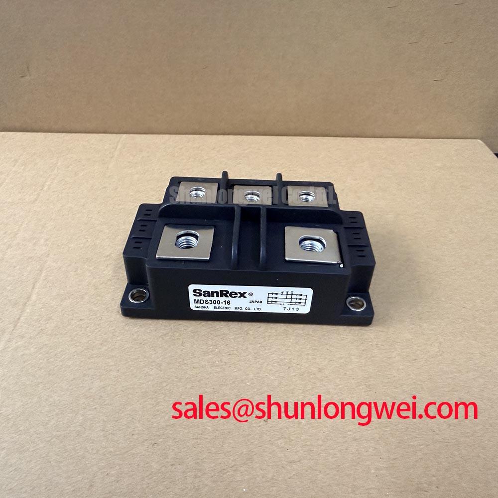
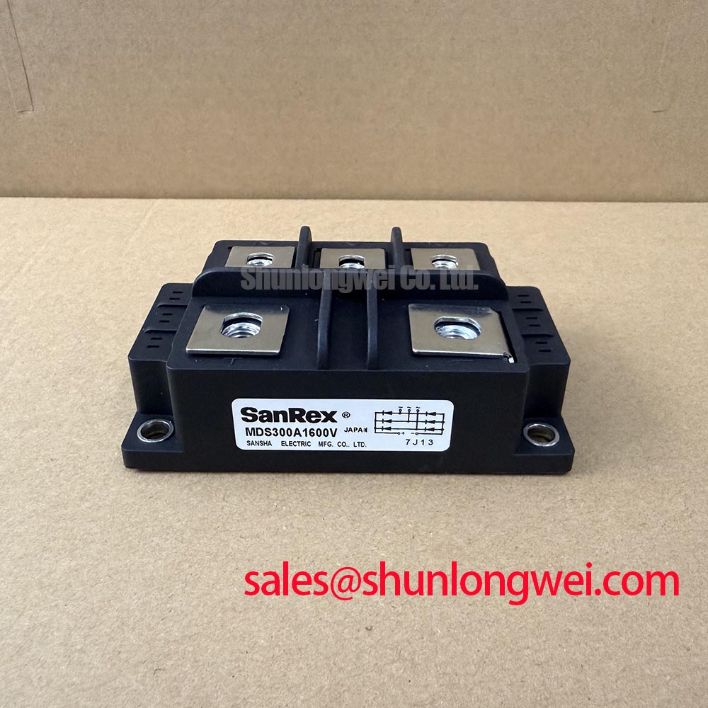
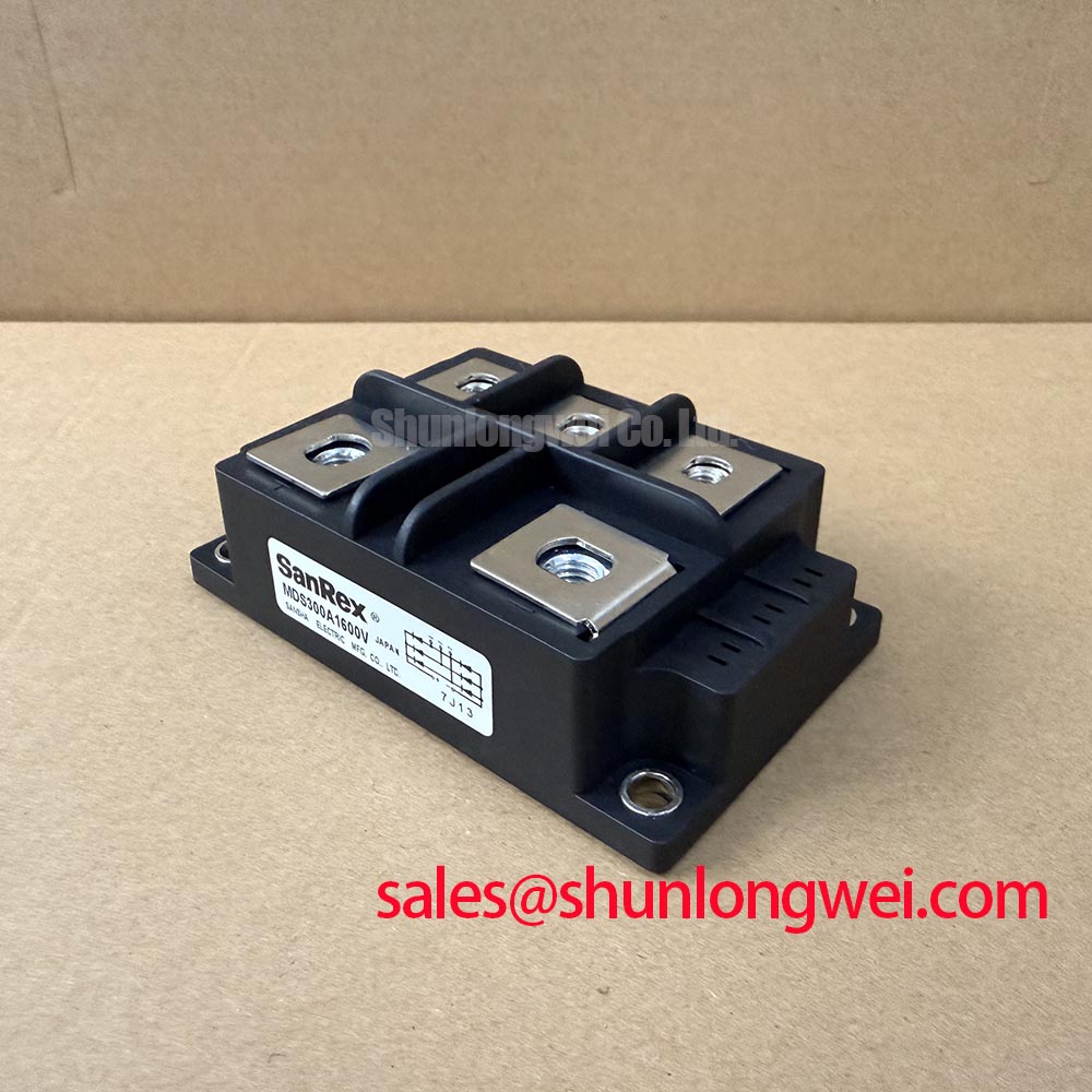
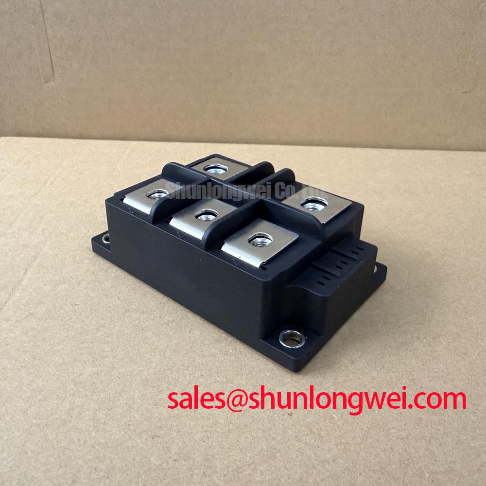
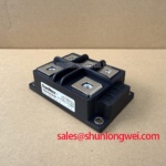
MDS300A1600V | Manufacturer: SanRex | Category: Bridge Rectifier Module | Rated voltage: 1600 V (Official Specification) | Rated current: 300 A (Official Specification) | Housing: Three-Phase Rectifier Case (Official Specification)
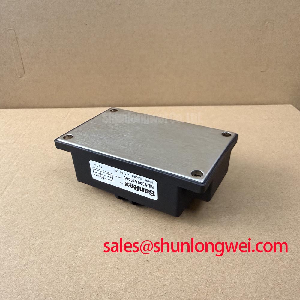
Inspect the heatsink contact area and the MDS300A1600V base for uneven paste transfer when a rectifier position runs hotter than its comparable positions. A heavy deposit at one edge and little contact at the other calls for a check of mounting flatness, fastener seating and heatsink condition. Clean the mating surfaces before reassembly, then spread thermal interface material uniformly without treating a thick layer as a cure for poor contact.
The 300 A rating is an Official Specification, not a promise that every installation can carry that current at its actual ambient temperature. As a Design Consideration, compare measured case temperature and operating current with the system’s thermal limits. Do not assign a junction-to-case thermal resistance, paste thickness or mounting torque to this model without its applicable mechanical documentation. Record the existing fastener arrangement and check that tightening leaves the housing seated evenly rather than distorted.
Field Alert: Do not reuse a mounting torque from another module solely because its case looks similar.
At the terminals, look for discoloration, loose connections and cable strain while the equipment is isolated. A warm connection can complicate a thermal diagnosis even when heatsink contact is sound. SanRex provides broader manufacturer context for its power semiconductor modules; use the documentation applicable to the installed assembly for its mounting and thermal limits.
MDS300A1600V Operational Boundaries: Checking Current Rise and Voltage Transients
Capture the rectifier input and output waveforms during a controlled restart if protection trips coincide with energization. Compare the trace with a known-good operating record, paying attention to current rise, ringing and peak voltage at the module terminals. The 1600 V rating is an Official Specification; the allowable transient behavior of the complete circuit still depends on its source, wiring and protection arrangement.
An RC snubber or series reactor, where the equipment already uses one, should be inspected as part of that circuit rather than sized from the module’s voltage and current ratings alone. As a Design Consideration, select any revised suppression network against measured transients and system losses, then verify it through switching tests. Check the installed snubber components and their connections before attributing an unexpected waveform to the rectifier.
For a proposed replacement, compare the case footprint, terminal layout, connection diagram and protection coordination alongside the electrical ratings. MDS500-12 is a reference for that comparison, not an established drop-in substitute. A grid-tied static var compensator is one possible equipment context, but the rectifier’s position and required behavior must be traced on that equipment’s schematic. A Vienna rectifier is a distinct active three-phase topology; its control assumptions should not be applied to this bridge solely because both involve three-phase rectification.
MDS300A1600V Circuit Protection: Separating Rectifier Checks from Firing-Circuit Checks
Measure cold-state terminal paths with the DC link discharged and the module isolated enough to avoid readings through parallel circuitry. Compare like-for-like paths using the equipment schematic and a known-good assembly where available. An unexpected reading warrants further isolation and measurement; it does not, by itself, identify the failed part. Confirm terminal identity from the applicable connection drawing before reconnecting cables.
Pulse-transformer firing, gate rise time and holding pulses belong to a controlled thyristor circuit. The supplied MDS300A1600V specifications identify a bridge rectifier module but do not establish gate terminals or a firing-pulse requirement for this model. If the surrounding equipment contains a separately fired thyristor stage, examine its pulse traces at that stage’s specified terminals and assess them against that stage’s documentation. Do not apply a gate-current target to the rectifier on the basis of the shared enclosure.
Trace the supply and protection path between the rectifier and adjacent power devices. A device such as 2RI100G-160 can be considered in a system-level parts review, but its electrical role and compatibility require the equipment schematic and its own specifications. Likewise, fuse coordination calls for the fuse characteristic and the rectifier’s applicable surge and energy limits; the 300 A rating alone cannot establish a fuse choice.
MDS300A1600V Thermal and Electrical Checks After a Surge Event
Record the fault waveform and inspect the rectifier’s terminal paths after a surge trip before returning the equipment to service. Compare the event with the fuse operation record and with the normal startup trace. Repeated trips call for checks of the load, upstream supply and protective components as well as the module; a cold-state meter check cannot establish remaining surge capability.
A sinusoidal half-cycle surge rating, often identified as ITSM, must be read with its stated waveform, initial junction temperature and recovery conditions. No ITSM value or fuse coordination table is supplied here for MDS300A1600V, so neither a permissible surge current nor a repetitive-event allowance can be inferred from its 300 A rating. As a Design Consideration, compare the documented rectifier limits with measured fault current, fuse clearing behavior and the temperature reached before voltage is reapplied.
On equipment that also uses an inverter, keep its gate-drive and desaturation checks separate from this rectifier inspection. The industrial drives IGBT technical analysis provides context for that different switching stage, not specifications for this bridge. Close the rectifier investigation by logging terminal readings, heatsink contact observations and restart waveforms against the equipment’s service record.