
Content last revised on September 17, 2026
Benchtop Waveform Tuning: Managing Thermal and Surge Stress on 2RI100G-160
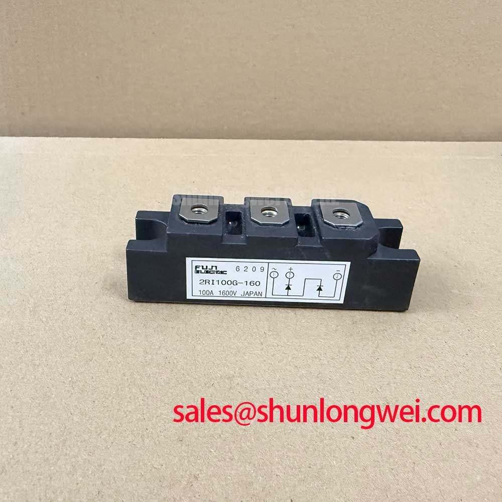
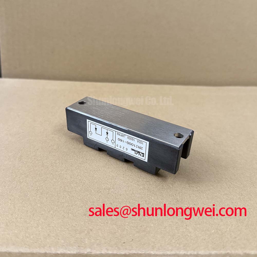
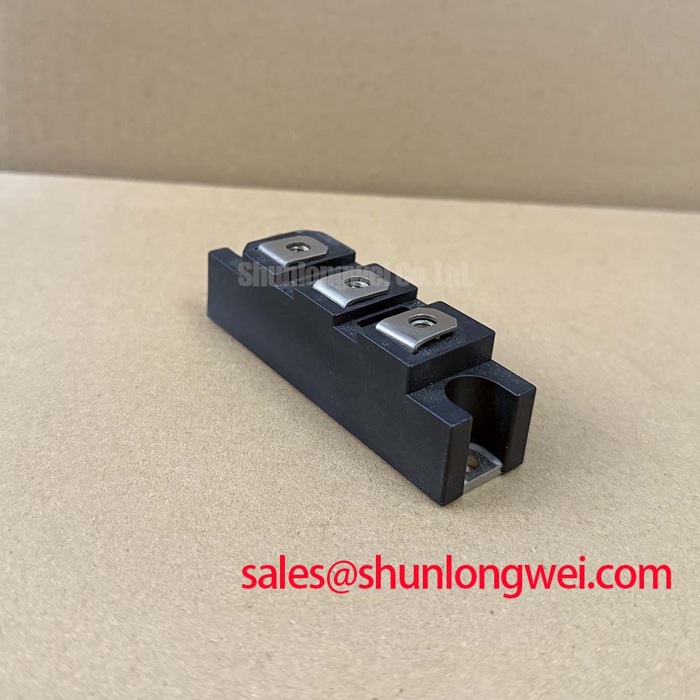
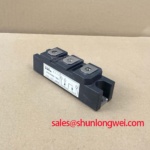
With the equipment isolated and discharged, first verify that the installed module nameplate matches 2RI100G-160, then inspect its terminals, mounting face, and connected busbars for heat discoloration, looseness, contamination, or mechanical strain before applying any electrical test. This Fuji Electric diode module is specified at VRRM 1600 V and IO 100 A at Tc 98 C. Its stated thermal and surge limits make the original circuit conditions, heat path, fuse coordination, and mechanical installation essential checks during repair assessment.
| Official Specification | Value |
|---|---|
| Repetitive peak reverse voltage, VRRM | 1600 V |
| Average output current, IO, at Tc 98 C | 100 A |
| Surge forward current, IFSM, 10 ms half sine wave | 1200 A |
| Operating junction temperature, Tj | −40 C to +150 C |
| Isolation voltage, AC for 1 minute | 2500 V |
| Forward voltage drop at IFM 320 A | 1.40 V |
| Repetitive peak reverse current at Tj 150 C and VR = VRRM | 30 mA |
| Thermal resistance, junction to case, Rth(j-c) | 0.20 C/W |
| Thermal resistance, case to fin with grease, Rth(c-f) | 0.10 C/W typical |
The 1200 A 10 ms half sine surge-current rating is an Official Specification for a defined nonrepetitive event. It is not a continuous current rating, a fuse-selection value, or confirmation that repeated fault clearing will be harmless. Before returning a rectifier section to service, compare the installed semiconductor fuse documentation and recorded event history with the original circuit. The protection path must clear prospective fault energy before the module experiences a destructive overload.
For a disconnected module, use a meter test that is appropriate for the instrument and record the result in both polarities between every accessible power-terminal pairing. A diode path should be evaluated against the known circuit arrangement or a verified matching unit, because external snubbers, parallel paths, capacitor discharge resistors, and busbar connections can distort in-circuit readings. A low resistance in both directions or no expected diode response can justify further isolation and test work, but neither observation alone establishes a single failure mechanism.
The specified 1.40 V forward voltage at 320 A is an Official Specification under its stated test condition. It should not be treated as a handheld-meter acceptance threshold. Forward behavior varies with test current and junction temperature. During controlled recommissioning, a technician can monitor thermal response, voltage waveform quality, and current sharing in the complete power path, then stop the test if the observed behavior departs from the known healthy installation.
The published Rth(j-c) of 0.20 C/W and Rth(c-f) of 0.10 C/W typical with grease identify the importance of the interface from die to heatsink. The case-to-fin figure is a typical value, not an installation guarantee. As a Design Consideration, clean the heatsink contact plane, remove old debris without damaging the base, and use a uniform thin thermal interface layer compatible with the original maintenance procedure. Verify flatness, clamping pattern, airflow, liquid-flow condition where applicable, and actual heat-sink temperature under the intended load.
Field Alert: De-energize, lock out, and verify discharge before loosening busbars or touching the module terminals, because stored energy in the DC link can remain hazardous after the supply is opened.
Assembly Integrity & Layout Architecture: Implementing AC-to-DC Transfer Characteristics for 2RI100G-160
The 2RI100G-160 is a diode module, so it has no gate terminal and does not set firing angle. In an SVC or thyristor-switched capacitor installation, firing-angle behavior belongs to the controlled thyristor section and its firing electronics. The diode module must instead be assessed according to its actual rectification or freewheel role, terminal topology, voltage exposure, thermal conditions, and fault-protection coordination. This distinction prevents an incorrect gate-drive troubleshooting path on a passive rectifier device.
Where phase-controlled equipment changes its firing angle from 0 degrees toward 150 degrees, the AC-to-DC transfer characteristic, displacement power factor, reactive demand, and harmonic behavior are determined by the complete topology. The system integrator should verify actual DC-link waveform, commutation conditions, source impedance, capacitor bank configuration, and controller timing against the original equipment documentation. The module’s 1600 V repetitive peak reverse-voltage rating remains an Official Specification that should be checked against measured peak reverse stress, including switching and network-transient conditions.
Terminal architecture deserves the same attention as semiconductor rating. Before fitting a replacement, compare the mechanical outline, terminal positions, polarity arrangement, conductor reach, insulation clearances, and original mounting sequence. A busbar forced sideways onto a terminal can introduce mechanical stress and a poor electrical joint even when the part number is correct. Tighten hardware using the original equipment documentation and the applicable fastener specification. Mounting torque is a Design Consideration governed by the screw size, hardware stack, terminal design, and manufacturer instructions rather than a value established by the provided module specifications.
Layered positive and negative conductors are commonly considered where a power loop must minimize parasitic inductance. This is a Design Consideration intended to reduce inductive voltage overshoot during changing current. The final geometry must be verified by the system engineer through measured switching waveforms and by confirming peak margins against the DC-link voltage. For general technology context on managing heat paths in power assemblies, see The Advanced Thermal Management Revolution.
In equipment where the original bill of materials identifies a related rectifier-stage device, 2DI100A-120 can be reviewed as a separate peripheral topology reference. Its presence does not establish interchangeability, and any substitution decision requires confirmation of circuit function, electrical limits, package fit, and connection arrangement.
Assembly Integrity & Layout Architecture: Implementing IEC 61000-4-5 Industrial Surge Immunity for 2RI100G-160
IEC 61000-4-5 describes system-level surge-immunity test methods; it is not a standalone certification claim for this diode module. A module rated at 1600 V VRRM must be evaluated inside the complete assembly, including incoming protection, conductor routing, line impedance, grounding architecture, control wiring, and enclosure. The system designer should confirm whether the installed SVC or capacitor-switching equipment has a documented IEC 61000-4-5 requirement and test the finished equipment under its applicable conditions.
Metal-oxide varistors, RC snubbers, surge arresters, and coordinated fuses are application-level protective elements. Their selection cannot be derived from VRRM alone. As a Design Consideration, position protection to limit the transient reaching the semiconductor while accounting for the upstream source, conductor length, repetitive-energy exposure, and the clamping behavior of the complete circuit. Validate the result on the intended hardware with suitable high-voltage differential measurement methods rather than assuming a catalog rating represents the waveform at the diode terminals.
Inspect snubber capacitors, resistor bodies, arresters, fuse clips, and cable termination points while the system is offline. Signs of heat exposure or a loose joint may indicate that the protective network needs inspection, but they do not prove the root cause without circuit measurements. Where a diode in the original rectifier chain has been identified as a replacement candidate, 2DI100Z-140 is available for objective specification comparison. Confirm topology, voltage and current ratings, thermal interface, terminal configuration, and original engineering approval before determining whether it is suitable for the position.
For manufacturer technology information relevant to power-semiconductor application evaluation, consult Fuji Electric Global Power Semiconductor Technologies. Installation decisions remain dependent on the original equipment circuit and the verified operating conditions.
Benchtop Waveform Tuning: Mitigating Stress during High di/dt Operation on 2RI100G-160
Gate-pulse rise time, holding current, back-porch behavior, and multipulse firing sequences are not applicable parameters for the 2RI100G-160 because this is a diode module. Those checks belong to the associated thyristors and firing-control channels within a phase-controlled SVC or thyristor-switched capacitor system. Keeping the diagnostic boundary clear avoids applying gate-drive assumptions to a device with no gate control function.
The relevant waveform work for this diode module is to inspect the current path and reverse-voltage behavior at the module terminals under safe, controlled conditions. Rapid current transitions elsewhere in the assembly can couple through loop inductance and place transient stress across rectifier devices. As a Design Consideration, minimize unnecessary loop area and verify terminal voltage using measurement equipment with appropriate bandwidth, insulation rating, probe placement, and reference method. The system engineer should determine acceptable peak conditions from the original design limits and measured waveforms.
Long conductors between switching sections, capacitor banks, and rectifier assemblies can introduce reflected or ringing waveforms. The actual result depends on cable impedance, routing, source waveform, connected loads, and damping components. Do not presume a fixed voltage multiplier from cable length alone. Measure the installed waveform at the relevant node, compare it with a known healthy circuit where available, and review snubber and clamp condition before attributing the behavior to the diode module.
After reassembly, bring the equipment up through its approved commissioning process while monitoring current, voltage, thermal response, and protection status. The −40 C to +150 C operating junction-temperature range and 2500 V AC isolation voltage for one minute are Official Specifications, but they do not replace system-level clearance checks, insulation verification, controlled surge testing, or the original equipment’s protection settings. This approach keeps the replacement assessment tied to measurable module boundaries and the real conditions of the power assembly.