

Content last revised on September 26, 2026
IXYS VVZ 175-14 IO7: Replacement and Installation Checks
Verify the nameplate against the replacement record, inspect the VUO/VUB Case for cracks or displaced terminals, and perform a de-energized terminal inspection before installing VVZ 175-14 IO7.
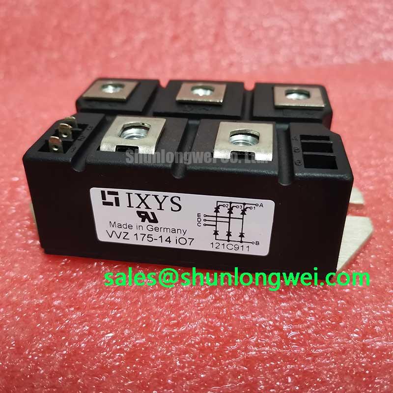
IXYS VVZ 175-14 IO7 is a bridge rectifier module specified at 1400 V and 175.0 A, with a VUO/VUB Case. These are product specifications for identification and application screening. They do not, by themselves, define the allowable operating current under every cooling condition, surge profile, switching frequency, or enclosure temperature.
For a medium-frequency induction melting and hardening furnace, the practical replacement task is to confirm the electrical position of the rectifier in the power topology, compare the original terminal arrangement, and verify the surrounding protection network. The system integrator should confirm the original circuit documentation before applying mains voltage, especially where the module feeds a DC link, capacitor bank, inverter stage, or controlled heating supply.
Assembly Integrity & Layout Architecture: Coordinating Fuse Clearing I²t with VVZ 175-14 IO7
A semiconductor fuse must be coordinated with the rectifier assembly using the actual fuse clearing characteristics and the rectifier’s published short-circuit withstand data. The 175.0 A rating of this module is an electrical rating, not a fuse selection value. Fuse coordination requires the applicable manufacturer data for total clearing I²t, prospective fault current, pre-arcing energy, and the device’s permitted surge withstand. Those values are not included in the supplied product information and should not be inferred from the nominal current rating.
During a dead-short investigation, isolate the module and inspect the fuse, busbar joints, capacitor bank, contactors, and semiconductor terminals as one protection chain. A fuse that has cleared does not prove that the bridge remained within its permitted thermal and mechanical stress limits. Conversely, a visually intact fuse does not confirm that the rectifier is electrically sound. Use the equipment schematic to identify whether the fault occurred on the AC input, rectified DC side, or downstream inverter branch.
Minimize the physical loop formed by the AC conductors, rectifier terminals, fuse, and DC-link connection where the system layout permits. This is a design consideration for limiting parasitic inductive overshoot during abrupt current interruption. The final arrangement must be checked by the system engineer with appropriate voltage and current measurements under controlled test conditions. The supplied data does not establish a guaranteed fuse class, fuse current, I²t limit, or fault-clearing time for this model.
Terminal hardware should be clean, mechanically stable, and matched to the original conductor and busbar arrangement. Check for darkened copper, loosened hardware, flattened washers, and evidence of heating at the module terminals. ⚠️ Field Alert: isolate and discharge the equipment according to its service procedure before touching the rectifier, fuse, or DC-link connections.
Assembly Integrity & Layout Architecture: RC Snubber Network Optimization for VVZ 175-14 IO7
RC snubber selection is system-specific. The supplied parameters identify 1400 V, 175.0 A, and the VUO/VUB Case, but they do not specify an RC network, resistor value, capacitor value, damping target, or saturable reactor requirement. Designers should first determine whether the rectifier is exposed to repetitive commutation transients, transformer leakage inductance, capacitor-bank resonance, or inverter-generated feedback.
For a furnace supply, inspect the complete commutation path rather than placing a snubber across the module by assumption. The transformer, input reactor, fuse, cable length, busbar geometry, DC-link capacitor, and switching bridge can all influence the measured waveform. A suitable engineering evaluation compares the voltage at the rectifier terminals with the voltage at the upstream and downstream nodes during energization, current transfer, fault interruption, and controlled shutdown.
Minimize parasitic loop inductance to reduce turn-off overshoot, while ensuring that any RC network does not create excessive reactive current, resistor heating, or unwanted resonance. The component values should be calculated from measured waveforms and then validated against the voltage, pulse-energy, insulation, and temperature limits of the selected resistor and capacitor. No specific snubber values should be assigned to this module without the circuit topology and transient measurements.
Long cables between a rectifier-fed DC section and an inverter or heating load can produce reflected-wave behavior when the cable impedance and termination are poorly controlled. This is a design consideration, not a confirmed characteristic of the module. If the oscilloscope shows a repeated high-frequency ring at the rectifier terminals, compare it with the known-good waveform and review cable routing, return paths, busbar overlap, and suppression placement before changing the rectifier.
When the application uses several rectifier paths in parallel, verify both static current sharing and dynamic current transfer. Small differences in conductor resistance, inductance, fuse impedance, or thermal coupling can affect sharing. The system engineer should validate the current in each path under the intended furnace load rather than assuming that the total current divides equally.
Benchtop Waveform Tuning: Mechanical Mounting and Thermal Checks for VVZ 175-14 IO7
Mechanical installation directly affects the thermal path from the VUO/VUB Case to the heatsink. The product information supplied here does not include case dimensions, baseplate flatness, thermal resistance, permitted mounting torque, or a thermal interface specification. Those values must be taken from the applicable IXYS mechanical and thermal documentation or the original equipment service record.
Before fitting a replacement, remove old interface material without scoring the mounting surface. Check the heatsink for burrs, distortion, contamination, and local high spots. Apply only the interface material and quantity permitted by the relevant mechanical instructions. Excess compound can reduce mechanical stability or migrate toward electrical surfaces, while insufficient coverage can create localized thermal resistance.
Use a controlled, even tightening sequence appropriate to the fastener arrangement. The correct torque is determined by the module hardware, screw size, thread condition, washer arrangement, and manufacturer instructions; it should not be guessed from the current rating. After tightening, confirm that the module body is seated without visible distortion and that the busbars do not impose side load on the terminals.
On the bench, begin with de-energized resistance and continuity checks against a known-good assembly where available. These checks can identify an obvious short or open condition, but they cannot reproduce reverse recovery, commutation, surge, or thermal behavior. During a controlled powered test, monitor the rectifier terminal waveform, DC-link rise, phase current balance, and heatsink temperature. The acceptance limits must come from the equipment design and the applicable IXYS documentation.
For a phase-controlled rectifier, the firing or conduction angle influences DC output and input-current distortion. Harmonic mitigation is a system-level task involving the transformer, line reactor, control strategy, filtering, and local grid requirements. The bridge module should not be described as independently compliant with EMC or power-quality standards. Measure the installed furnace system under representative operating conditions.
Transient Dynamics & Electrical Design: Evaluating Post-Surge Reverse Voltage Blocking on VVZ 175-14 IO7
Post-surge assessment requires the original surge-current and recovery specifications for the exact device configuration. The supplied data confirms a 1400 V voltage rating and a 175.0 A current rating, but it does not provide the sinusoidal half-cycle surge value, ITSM, junction-temperature limit, reverse-voltage recovery data, or repetitive surge duty. These values must be verified before using the module in a high-energy rectifier test.
After an upstream fault or line surge, do not reapply voltage solely because the fuse has cleared and the module has no visible damage. Inspect the AC terminals, DC terminals, heatsink interface, fuse carrier, transformer connection, and capacitor bank. A controlled insulation and semiconductor test may help locate a hard failure, while a waveform test is required to evaluate transient stress that remains hidden during a simple cold check.
Reapply power only under the equipment’s approved commissioning procedure, with current limiting and suitable measurement isolation. Record the three-phase input behavior, rectified output rise, DC-link stability, and any abnormal acoustic or thermal response. If the system uses a precharge circuit, verify its operation before exposing the rectifier to the full DC-link energy.
For induction melting or hardening equipment, the rectifier is evaluated as part of a wider power conversion chain. Transformer leakage, line impedance, capacitor-bank switching, inverter commutation, and busbar geometry can all influence reverse-voltage stress. Designers should verify peak voltage margins during switching and surge tests against the actual system limits, rather than treating the module’s nominal voltage rating as a substitute for transient coordination.
For cross-model evaluation, engineers may review the neutral product information for SKD 25/14, but electrical, mechanical, thermal, and terminal compatibility must be established from the respective documentation before any substitution is considered. Broader power-conversion architecture can also be reviewed in The Race for Efficiency.