

Content last revised on October 1, 2026
Preventing Spurious Faults: Thermal Interface Material Spreading Guidelines for 2DI150A-120
| Manufacturer | Fuji Electric |
|---|---|
| Model | 2DI150A-120 |
| Product Category | Diode Module |
| Package | Power Diode Module |
| Rated Voltage | 1200.0 V Official Specification |
| Rated Current | 150.0 A Official Specification |
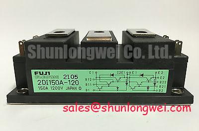
Inspect the copper baseplate contact pattern immediately after removing the module from the heatsink, looking for dry areas, displaced thermal interface material, or localized pressure marks. The 2DI150A-120 is a 1200.0 V, 150.0 A Fuji Electric power diode module; its thermal path depends on consistent mechanical contact between the baseplate and heatsink. The listed electrical ratings are Official Specification values, while the required thermal resistance and allowable junction temperature must be taken from the applicable Fuji Electric documentation for the exact production variant.
Clean both mating surfaces using an approved process and apply thermal interface material as a thin, even layer suitable for the selected heatsink finish. Tighten the mounting hardware progressively across the module mounting points so the baseplate does not bow during assembly. Mounting torque is a Design Consideration determined by the module hardware, fastener size, washer arrangement, and manufacturer instructions; it must not be inferred from the 1200 V or 150 A rating.
After installation, verify that the heatsink is seated without rocking and measure the temperature distribution during a controlled current test. A rising temperature gradient near one edge may indicate uneven contact, insufficient clamping, airflow imbalance, or an overloaded electrical path. Fuse coordination must also be checked against the documented module I2t capability and the selected semiconductor fuse. No I2t or Rth(j-c) value is stated here because those values require the applicable factory data.
Assembly Integrity & Layout Architecture: Integrating 2DI150A-120 with Pulse-Transformer Isolated Firing Circuits
Trace the terminal wiring and measure the voltage waveform directly at the module connection points before attributing a soft-starter firing problem to the diode module. The 2DI150A-120 is identified as a diode module, so it does not provide a gate terminal or a gate-firing characteristic. Pulse-transformer firing requirements, gate pulse rise time, holding current, and multi-pulse firing schemes apply to separately controlled thyristor devices in the wider soft-starter topology, not to this diode module itself.
Keep high-current forward and return paths physically ordered and symmetrical where the equipment topology permits. This Design Consideration reduces unwanted loop coupling and makes phase-to-phase waveform comparison more meaningful during commissioning. When a pulse transformer controls an adjacent controlled-semiconductor stage, verify pulse amplitude, isolation, polarity, timing, and reset behavior at the controlled device terminals using an isolated measurement method. Do not transfer those measurements to the diode module as though it were a gated component.
The related 2DI300A-050 may be evaluated as a separate rectifier element within a system topology, but compatibility depends on voltage stress, current duty, mechanical interfaces, fuse coordination, and the original circuit documentation. Terminal identification and tightening requirements must be checked against the exact device documentation before energization.
2DI150A-120 Operational Boundaries: Evaluating Transient Voltage Stress and RC Damping
Capture the voltage across the relevant diode paths and the switching-node waveform during start, stop, and fault-clearance events, paying particular attention to overshoot and ringing at the moment of current interruption. The 1200.0 V rating is an Official Specification limit for the device, but it does not by itself define an acceptable transient waveform, repetitive peak stress, reverse-recovery behavior, or system insulation margin.
RC damping networks and any series saturable reactor should be selected from measured parasitic inductance, switching frequency, fault current, and the complete commutation path. This is an Engineering Recommendation: the network must be validated against actual peak voltage, resistor pulse energy, capacitor dielectric rating, and thermal duty. Designers should minimize the high-current commutation loop and confirm the resulting waveform with a properly rated differential probe.
Reverse-recovery softness and the associated EMI behavior must be established from the applicable Fuji Electric dynamic data or measured under representative current and temperature conditions. A generic softness factor cannot be assigned to this model without a source. The The Ultimate IGBT Knowledge Base provides broader switching and power-loop reference material, while the Fuji Electric Power Semiconductor and IPM Modules resource should be used for manufacturer-level product context.
Field Diagnostics & Commissioning: Thermal and Surge Margins during High-Current Events in 2DI150A-120 Topologies
Record phase current, heatsink temperature, and the voltage across each relevant diode path during a controlled commissioning cycle before increasing operating duty. The 2DI150A-120 carries an Official Specification current rating of 150.0 A, but continuous current capability, surge current, and thermal limits depend on the exact factory datasheet conditions, heatsink arrangement, conduction angle, ambient temperature, and protection system.
For a short-circuit or severe overload investigation, compare the selected semiconductor fuse clearing characteristic with the documented I2t withstand value for the module. The fuse must interrupt the fault before energy and temperature exceed the device limits, while the mechanical assembly must withstand the associated electromagnetic forces. If the module has experienced a high-current event, inspect the terminals, baseplate contact, fuse condition, and phase symmetry before reverse voltage is reapplied.
Do not treat a measured resistance or a single cold-state diode reading as conclusive proof of device condition. Compare all diode paths using the same test polarity and instrument settings, then corroborate abnormal results with appropriately isolated voltage measurements and controlled current waveforms. Designers should evaluate the complete high-voltage insulation system, including terminal spacing, creepage, clearance, enclosure contamination, and the soft-starter bus structure. The Fuji Electric Global Power Semiconductor Technologies resource supplies manufacturer context for power-semiconductor evaluation.
Safety Note: Isolate and discharge the soft-starter DC and AC power paths before disconnecting the module or touching its terminals.