
Content last revised on October 24, 2026
1DI200A-120 Inspection and Commissioning
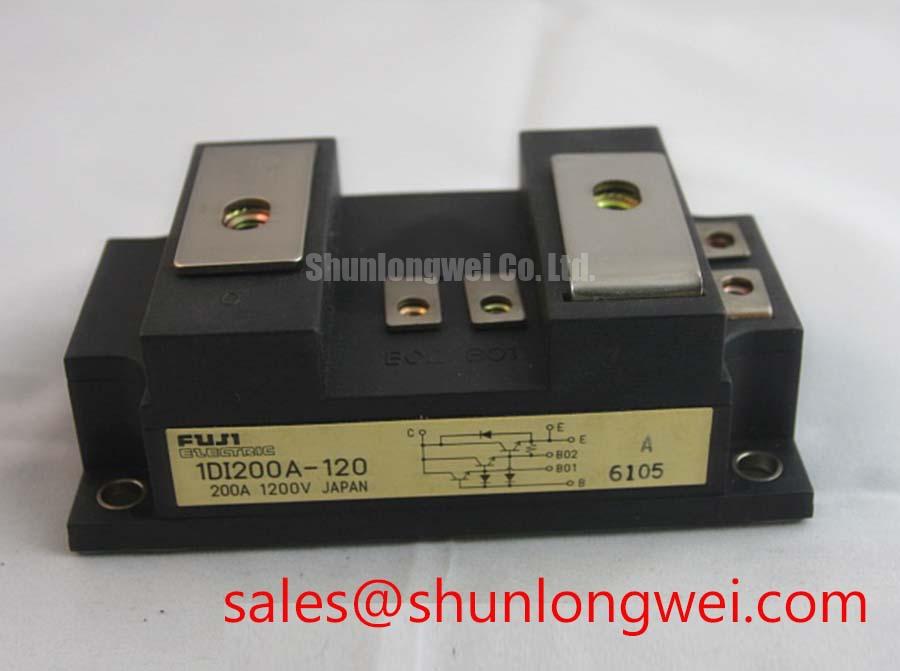
- Isolate the power stage, discharge stored energy, and identify collector, emitter, and base connections from the terminal diagram before measuring.
- Record cold terminal resistance with a four-wire micro-ohmmeter, separating bolted-joint resistance from semiconductor conduction paths.
- If a module diode is documented, compare diode-mode readings in both polarities with a known-good module under matching temperature and connection conditions.
- Inspect mounting surfaces, terminal alignment, and driver isolation before reconnecting the power circuit.
The 1DI200A-120 from Fuji Electric is a power transistor / Darlington module. Its bipolar control interface requires a base-drive assessment; IGBT gate-charge, Miller-plateau, and gate-resistor procedures cannot be transferred directly to this device. Incoming inspection should establish terminal identity and repeatable static measurements before powered evaluation.
| Parameter | Specified value | Bench interpretation |
|---|---|---|
| Collector-emitter voltage | 1200 V | Voltage rating; switching overshoot must remain within the applicable operating limits. |
| Continuous collector current | 200 A at a case temperature of 25°C | Case-temperature condition matters when assessing continuous loading. |
| Collector-emitter saturation voltage | 2.7 V typical | Compare only at matching collector-current and base-drive conditions. |
| Total power dissipation | 780 W | Thermal rating, rather than an unconditional operating-loss allowance. |
| Isolation voltage | 2500 V | Consult the datasheet for test duration, waveform, terminal grouping, and acceptance conditions. |
Field Diagnostics & Commissioning: Preventing Terminal Overheating in 1DI200A-120 Topologies
Place the micro-ohmmeter sense probes immediately across each bolted interface so the result represents the joint rather than an extended busbar section. As a Design Consideration, repeat measurements with consistent probe placement and temperature, then compare equivalent connections. An acceptance threshold belongs to the equipment’s qualified assembly procedure; a universal micro-ohm limit cannot establish joint integrity for every terminal arrangement.
Check for displaced washers, uneven seating, conductor strain, and surface contamination before tightening to the documented assembly requirements. During controlled loading, compare thermographic profiles at equivalent joints after temperatures stabilize. Differences in emissivity, viewing angle, airflow, and conductor geometry can distort apparent temperature, so an isolated hot image warrants electrical and mechanical investigation rather than an immediate failure diagnosis.
💡 Bench Tip: Keep the module de-energized during resistance and diode-mode checks, and record probe polarity alongside every cold reference reading.
For compatibility assessment in an industrial inverter welder or medium-frequency induction-heating supply, compare the original terminal arrangement, base-driver capability, switching duty, and cooling interface. The 1DI400MN-120 can enter that comparison, but its model designation alone does not establish a direct replacement relationship.
Assembly Integrity & Layout Architecture: Implementing Junction-to-Case Thermal Network Simulation for 1DI200A-120
Build the junction-temperature estimate from the actual loss waveform, measured case temperature, and manufacturer thermal-impedance information. As an Engineering Recommendation, use a multi-RC thermal network fitted to the relevant transient response when assessing repeated overload pulses. Preserve the distinction between junction-to-case behavior and the separate interface, heatsink, and cooling-path contributions.
The 780 W dissipation rating and 2.7 V typical saturation voltage do not establish a permissible pulse schedule. Conduction loss changes with collector current, temperature, and base excitation; switching loss adds a separate heat input. Evaluate pulse accumulation against the applicable junction-temperature and safe-operating-area limits, using thermal-model coefficients that represent this device.
For base-drive integration, assess forward drive, reverse charge extraction, driver dissipation, and turn-off storage behavior. Select damping components through measured switching behavior and the driver’s operating limits. Minimize the commutation-loop area to reduce inductive voltage overshoot, while maintaining equipment-required clearances. Driver-isolator common-mode immunity should be evaluated against measured switching transients, with attention to unintended base excitation.
When parallel operation is contemplated, compare static current distribution and switching timing under representative thermal conditions. Do not assume a positive temperature coefficient will ensure sharing in a Darlington assembly. The Ultimate IGBT Knowledge Base provides comparative switching-device background; device-specific thermal and protection limits remain essential to this bipolar implementation.
1DI200A-120 Operational Boundaries: Evaluating Commutation and Switching Limits
Trace the commutation path on the equipment schematic before interpreting diode-mode readings or reverse-recovery waveforms. Establish whether the measured diode belongs to the module or another circuit element; parallel paths can obscure an incoming-inspection result. A multimeter reading provides a static comparison, not a measurement of reverse-recovery current or diode softness.
As a Design Consideration, evaluate recovery-current peaks, current decay, and collector-voltage ringing together under representative switching conditions. Adjusting base-drive transitions or an RC snubber changes switching loss and stress, so component selection should follow measured waveforms and the system’s thermal budget. Voltage-monitoring protection likewise requires thresholds and shutdown behavior appropriate to a bipolar transistor’s operating area, including charge extraction during turn-off.
For isolation assessment, distinguish the 2500 V component rating from the equipment’s protective separation requirements. The reference on Safety Extra Low Voltage (SELV) and PELV electrical safety explains the system-level context. Any dielectric test should follow the approved procedure, with connected driver electronics protected from unintended test exposure.