
Content last revised on October 1, 2026
MDS300-16 Thermal-Electrical Optimization: Reverse Recovery Charge Practical Tuning
| Manufacturer | SanRex |
|---|---|
| Model | MDS300-16 |
| Category | Bridge Rectifier Module |
| Package | Three-Phase Rectifier Case |
| Rated Voltage | 1600 V |
| Rated Current | 300 A |
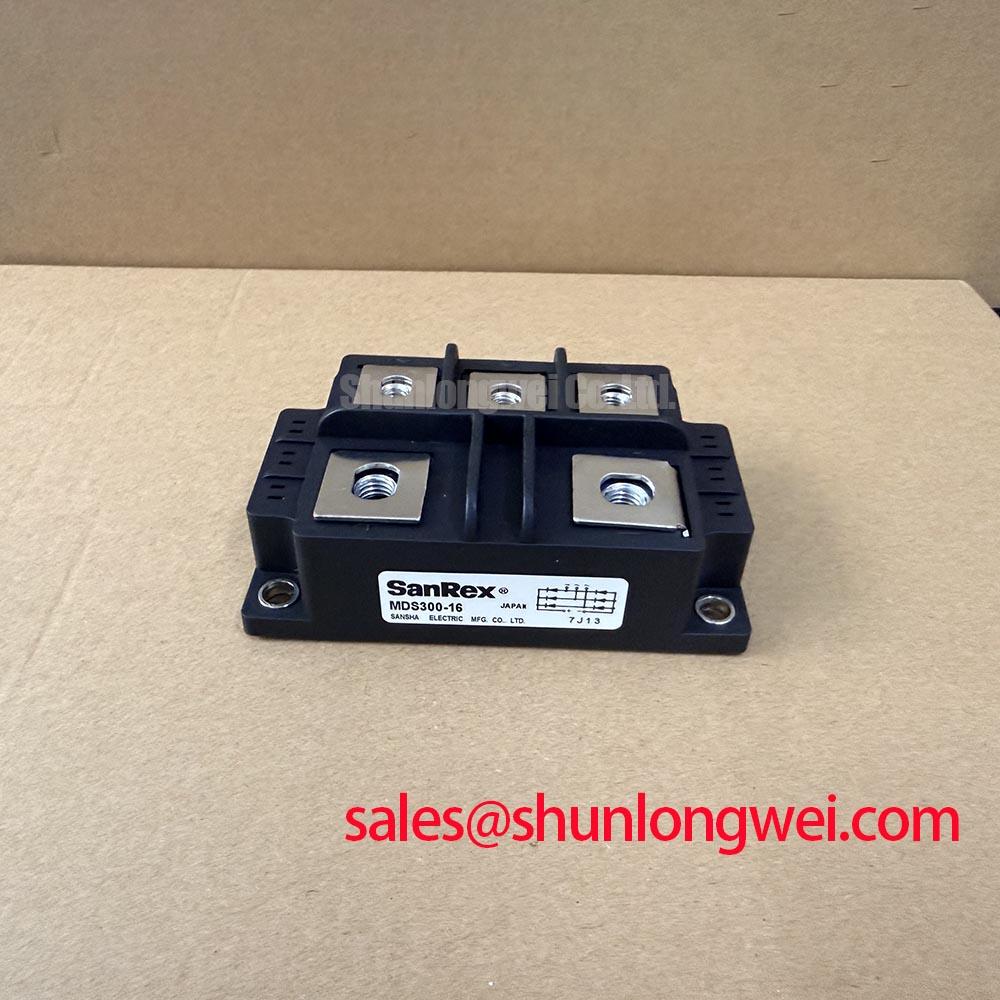
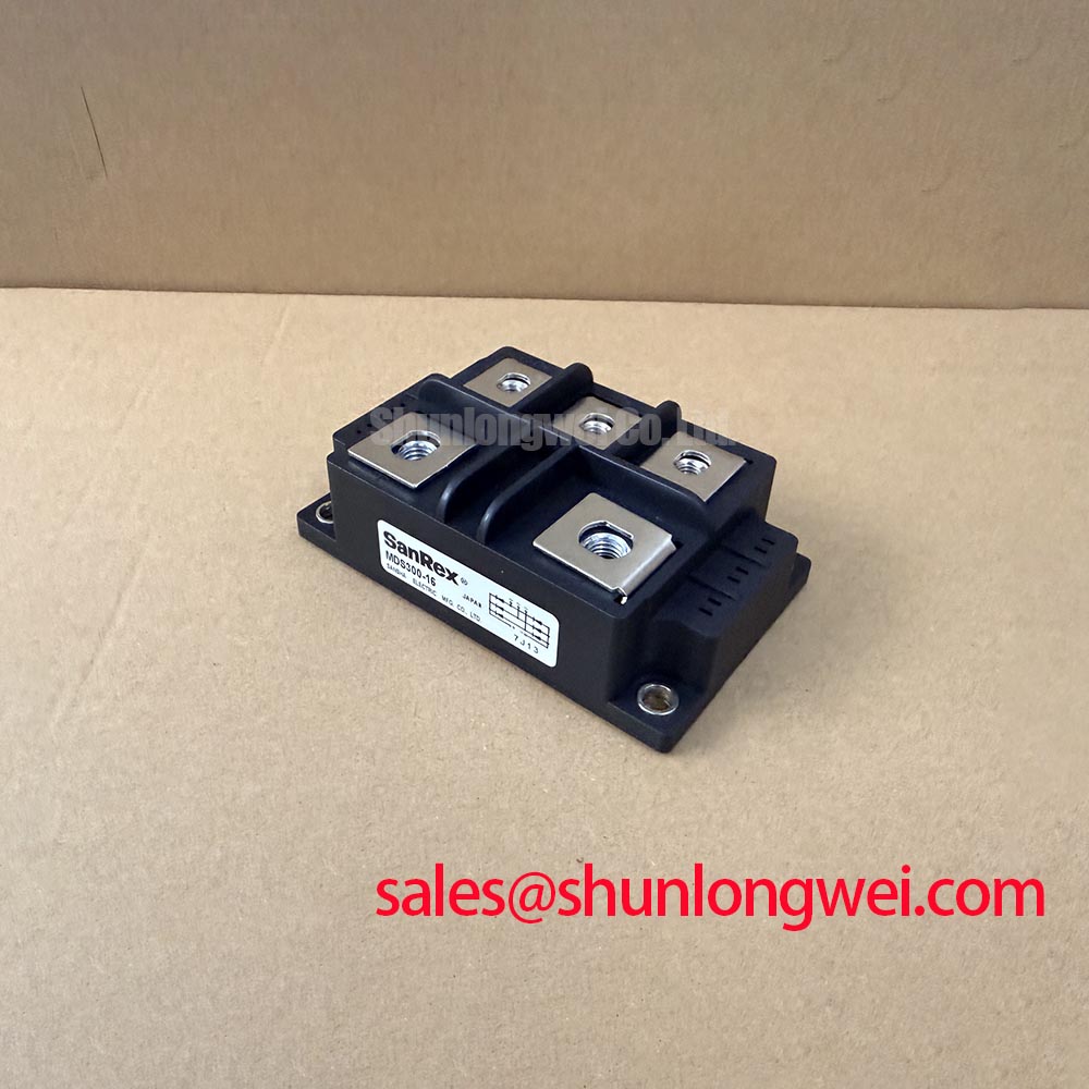
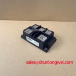
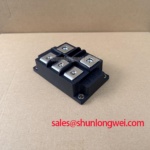
Measure the rectifier bridge terminals cold with the power isolated, then compare phase-to-phase readings and inspect the case for cracks, carbon tracking, loose hardware, or terminal distortion before waveform testing. The SanRex MDS300-16 is specified as a 1600 V, 300 A bridge rectifier module in a three-phase rectifier case. Those ratings establish the device identity and electrical boundary; they do not by themselves define reverse-recovery current, recovery time, fuse coordination, or allowable operating temperature.
For an induction melting or hardening furnace, capture commutation behavior at the rectifier output with a properly rated differential probe and current measurement method. Look for excessive recovery current, ringing, or a delayed return to blocking voltage. These observations can indicate interaction between diode recovery, transformer leakage inductance, busbar geometry, and the load-side converter. Treat the result as a system-level design consideration and compare it with the original machine waveform under equivalent load conditions.
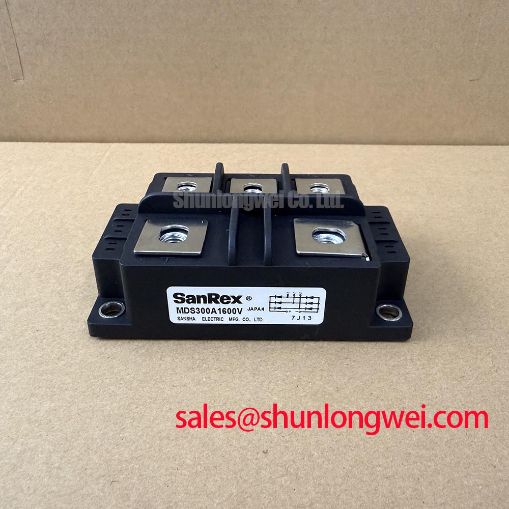
Use the manufacturer’s published application information for the applicable I2t fuse coordination, terminal arrangement, and mounting requirements. SanRex product information can be reviewed through the SanRex power semiconductor reference. An equivalent part under evaluation should be checked by package geometry, terminal layout, voltage rating, current rating, thermal interface, and the equipment’s protection scheme rather than by current rating alone. The MDS300A1600V may also be evaluated as a related replacement candidate when its complete mechanical and electrical compatibility has been confirmed.
MDS300-16 Thermal-Electrical Optimization: Critical Rate of Rise of Off-State Voltage Practical Tuning
Probe the rectifier output during energization and commutation to identify fast off-state voltage transitions, overshoot, and repeated ringing at the module terminals. The MDS300-16 carries a 1600 V rated voltage, but the complete furnace circuit must control transient peak voltage so that the semiconductor does not experience an unverified condition beyond its operating boundary.
An RC snubber, damping network, or series saturable reactor can be considered when measured dv/dt behavior produces unwanted turn-on or concentrated current stress. Component values must be selected from the measured circuit impedance, transformer characteristics, switching pattern, and protection requirements. This is an Engineering Recommendation, not an MDS300-16 factory parameter. Validate the finished network with high-voltage differential measurements at the module terminals and confirm that the added parts do not create excessive discharge current or thermal loading.
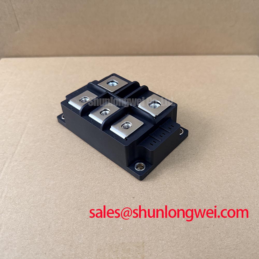
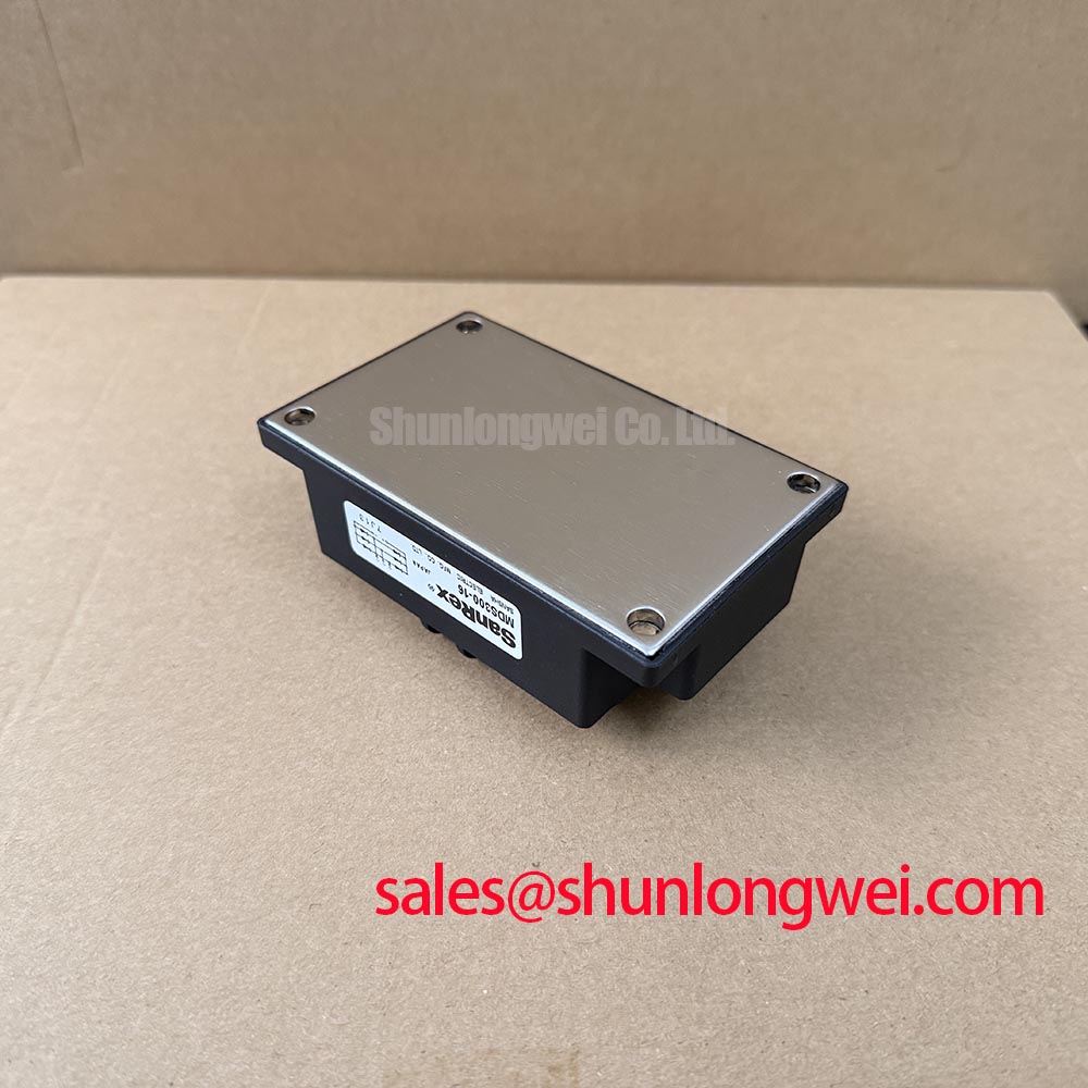
Inspect the main terminals for even contact pressure, clean mating surfaces, and mechanical movement after thermal cycling. The three-phase rectifier case must be mounted according to the original equipment mechanical specification, with the correct interface material and hardware sequence. Field Alert: isolate and discharge the furnace DC link before touching terminals, snubbers, fuses, or measurement probes.
When long conductors connect the rectifier to the next power stage, evaluate transmission-line reflection and bus inductance as possible contributors to voltage spikes. Minimize high-current loop area and verify peak voltage at the module, not only at a remote test point. The Vienna rectifier topology provides useful background for three-phase rectifier commutation and power-factor-correction behavior; its topology information is available from this technical reference.
MDS300-16 Thermal-Electrical Optimization: High-di/dt Gate Firing: Pulse-Train Timing Practical Tuning
Check the firing circuit at the controlled converter connected to the rectifier, and separate the bridge’s power terminals from any control-terminal assumptions before troubleshooting. The supplied factory data identifies the MDS300-16 as a bridge rectifier module, so gate pulse specifications such as gate current, pulse rise time, holding current, and pulse-train timing must not be assigned to this part without matching documentation.
In a furnace system that uses controlled semiconductor stages downstream, inspect the firing transformer or gate-driver wiring for excessive loop inductance, poor return routing, connector oxidation, and unstable reference potential. Observe the command and return signals together with the power waveform. Oscillation or irregular pulse amplitude may indicate a driver, isolation, grounding, or wiring problem rather than a defect in the MDS300-16 itself.
Designers should coordinate pulse timing with the converter control scheme, transformer leakage, commutation intervals, and measured load response. A multi-pulse firing strategy may be considered where the system architecture supports it, but the final pulse width, repetition, and damping must be verified on the actual equipment. Keep control wiring physically separated from high-current rectifier paths and confirm that the selected terminal connections match the original circuit drawing.
Benchtop Waveform Tuning: Mitigating Stress via Non-Repetitive Surge On-State Current on MDS300-16
Record the furnace start-up current and rectifier output waveform during a controlled bench or service test, then compare the measured inrush profile with the module’s 300 A rated current and the original protection coordination. The rating is an official product parameter; it is not a substitute for a verified non-repetitive surge-current rating, ten-millisecond half-cycle capability, or junction-temperature recovery window.
Before reverse voltage is reapplied after a surge event, allow the system’s measured thermal response and protection sequence to settle according to the equipment design. Check fuse condition, busbar joints, heat-sink contact, airflow or cooling path, and terminal discoloration. A single high-current event can alter contact resistance or protection behavior even when the module passes a simple cold resistance check.
Use the manufacturer’s applicable surge-current, thermal-resistance, fuse I2t, and mounting data when completing the final coordination review. Do not infer those values from the 1600 V and 300 A headline ratings. For high-duty thermal evaluation, the practical reference on advanced thermal management can support inspection of interface pressure, cooling symmetry, and heat-flow limitations.
For medium-frequency induction melting and metal hardening equipment, final acceptance should combine terminal waveform measurements, protective-device coordination, mechanical inspection, and repeated load testing under the machine’s actual operating sequence.