Content last revised on October 15, 2026
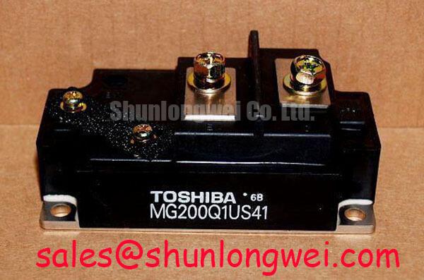
Toshiba MG200Q1US1 Identification and Cold-State Inspection
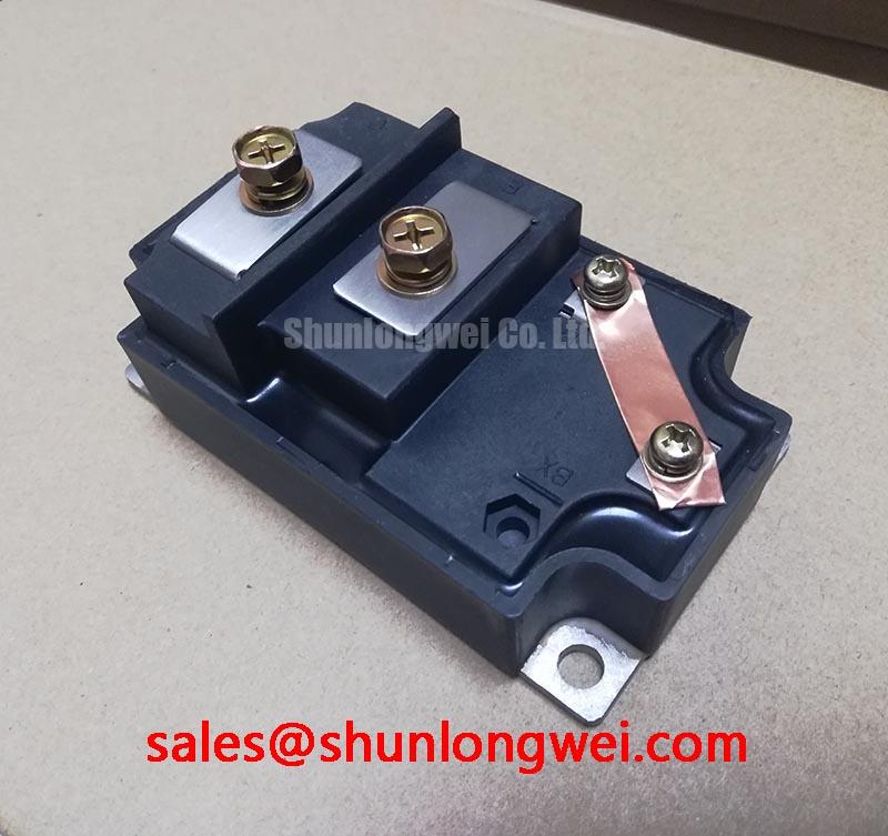
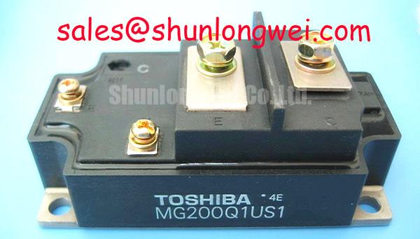
With the DC link isolated and discharged, match the module terminal markings to the equipment schematic before making cold-state measurements. The Toshiba MG200Q1US1 is an IGBT module with specified voltage and collector-current ratings of 600.0 V and 200.0 A, respectively, under the applicable datasheet conditions. Record the terminal arrangement, mounting footprint, and gate connections before evaluating its electrical fit.
For incoming inspection, use the multimeter diode range only across junction paths identified in the connection diagram. Record probe polarity, module temperature, and instrument settings; compare readings with a known-good reference under matching conditions. A diode-range reading alone cannot establish blocking capability, switching performance, or permissible surge current.
💡 Bench Tip: Use ESD-controlled handling and keep the gate referenced to the emitter during cold-state comparison so stored gate charge does not distort the readings.
MG200Q1US1 Operational Boundaries: Evaluating Transmission Line Impedance Mismatch
Measure switching waveforms at the inverter output and motor terminals separately when long motor leads are involved. Design Consideration: cable reflections can produce motor-terminal peaks approaching twice the incident voltage step under strong impedance mismatch; this is not a guaranteed multiple of DC-link voltage at the MG200Q1US1 terminals. Probe location, cable propagation time, switching edge speed, and load impedance determine what the oscilloscope captures.
Use appropriately rated differential probes with short connections, and compare the same operating event at both measurement locations. A motor-end reflected peak and a collector-emitter turn-off overshoot require different corrective work. Output reactors or dv/dt filters should be evaluated against cable characteristics, motor insulation requirements, load current, and switching conditions; their component values belong to the equipment design rather than the module specification.
Engineering Recommendation: preserve the equipment’s documented electrical clearances when repositioning busbars, output cables, or filter connections. Route power conductors away from gate wiring and avoid reducing terminal spacing through improvised adapters. Evaluate any layout change through measured waveforms rather than assuming that a shorter cable automatically resolves every transient.
When assessing compatibility with electric material-handling or forklift traction equipment, compare the existing power stage, drive interface, cooling arrangement, and mechanical connections. The MG75Q1ZS50 is a separate comparison candidate, not an established direct replacement: matching manufacturer names does not establish equivalent current capability, pinout, or switching behavior.
Benchtop Waveform Tuning: Mitigating Stress via Floating Gate Bias Supply Decoupling on MG200Q1US1
Observe the floating driver supply during startup, switching, and shutdown under controlled test conditions before approving normal operation. Design Consideration: the driver should maintain a defined off-state while its auxiliary supply establishes regulation, and its undervoltage interlock should prevent incomplete gate enhancement. If the equipment uses negative turn-off bias, assess that rail against the module’s gate limits and driver requirements rather than assigning a generic negative-voltage setting.
Place local driver decoupling so the gate-charge current has a compact return path, then check supply disturbance alongside gate-emitter voltage. Reverse-transfer capacitance, commonly identified as Cres, is not itself Miller charge; both influence switching analysis, but they are different datasheet quantities. Collector voltage transitions can couple current into the gate circuit, so inspect off-state gate excursions with a suitable measurement arrangement.
An active Miller clamp and collector-voltage active clamping serve different functions. The former restrains unintended gate rise; the latter modifies switching during an overvoltage event and can increase semiconductor dissipation. Engineering Recommendation: evaluate either function with the existing driver protection scheme and measured operating conditions, without treating it as an inherent MG200Q1US1 feature.
For parallel installations, compare static conduction behavior at controlled temperature and assess dynamic sharing during switching. A positive temperature coefficient of on-state voltage can assist sharing only in the operating region where it applies; it is not established here as a model-specific characteristic. Symmetrical power paths, comparable gate loops, and balanced cooling remain separate integration considerations. The Park transformation explains motor-control reference frames, not a module-level current-sharing guarantee.
MG200Q1US1 Circuit Protection & Reliability: Insulation Screening and Its Limits
Separate insulation-resistance screening from dielectric-withstand testing before connecting a tester between terminals and the baseplate. Design Consideration: these tests use different acceptance criteria, and neither justifies an arbitrary test voltage or resistance threshold. Use the manufacturer-approved terminal grouping, voltage, duration, and discharge procedure; disconnect vulnerable driver circuitry as the equipment service procedure requires.
Inspect accessible insulation surfaces for contamination, moisture, tracking, and damage around terminals and mounting interfaces. An abnormal insulation measurement warrants controlled investigation, but cannot by itself identify a ceramic microcrack or establish the module’s internal substrate construction. Preserve documented creepage paths and assess the effect of airborne dust through the equipment’s maintenance requirements.
For repeated overcurrent trips, capture the protection timing and thermal operating conditions before attempting another energized test. The 200.0 A rating does not establish diode surge-current capability, an ITSM limit, or a recovery interval after a fault. Those require their own specified conditions.
System-level discussions in Peak Efficiency in Solar and Energy Storage and the interleaved boost converter reference provide topology context, not MG200Q1US1 ratings. During troubleshooting, distinguish DC-link ripple from device switching overshoot before changing protection settings or repeating the insulation test.