
Content last revised on September 10, 2026
MG20G6EL2 Thermal-Electrical Optimization: Derating Guidelines and Mismatched Parameter Practical Tuning
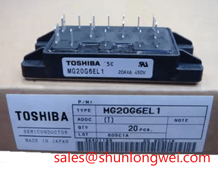
For a precision stepper or BLDC motor servo actuator, the first integration task is to compare the module’s 600.0 V and 20.0 A ratings with the actual DC link, phase current, switching pattern, ambient temperature, and cooling path. A nameplate current comparison alone is insufficient because conduction and switching losses depend on the gate drive, load waveform, commutation timing, junction temperature, and stray inductance. Designers should verify the full loss model with measured case temperature and switching waveforms rather than treating the official current rating as a universal operating point.
A Design Consideration for parallel operation is to keep the gate loop geometry and power path symmetrical. IGBT conduction characteristics commonly change with temperature, and a positive temperature coefficient in the relevant operating region can support steadier static current sharing. Dynamic sharing still depends on matched gate resistance, emitter routing, driver propagation delay, and commutation inductance. If the phase current appears unbalanced, compare gate to emitter waveforms at each device, then inspect busbar geometry, connector resistance, and thermal contact before assigning the condition to the module itself.
The electrically related MG150Q1JS40 may be reviewed as a neutral comparison point when the original equipment documentation calls for a different current class. It should not be treated as a drop-in replacement without checking topology, terminal assignment, mechanical dimensions, gate characteristics, and protection coordination.
Bench Tip: Use ESD controls and compare cold-state diode-mode readings with a known-good reference from the same approved documentation before connecting the module to a powered drive.
MG20G6EL2 Operational Boundaries: Evaluating High-Frequency Common-Mode Bearing Current Limits
Long motor leads can behave as a transmission-line problem rather than a simple resistive load. Reflections caused by impedance mismatch can increase terminal overshoot and place additional electrical stress on the switching devices, motor insulation, and cable shield system. The often-cited possibility of a terminal spike approaching twice the DC-link voltage is a system-level transmission-line consideration, not an MG20G6EL2 datasheet limit. Engineers should capture collector-emitter voltage at the module terminals during the fastest switching transitions and compare the measured peak with the documented device boundary.
Output filters, common-mode chokes, and cable termination methods should be selected only after examining motor cable length, characteristic impedance, switching edge behavior, grounding arrangement, and conducted noise. A filter that reduces bearing current can also alter switching loss or create resonant behavior. Confirm the complete drive response with an oscilloscope, current probe, and motor connected under representative conditions.
Fast semiconductor fuse coordination also requires more than comparing nominal current values. The fuse clearing I²t, prospective fault current, DC-link energy, module surge capability, and gate-driver shutdown delay must be evaluated as one protection network. The MG20G6EL2 official data supplied here confirms 600.0 V and 20.0 A ratings, but it does not establish a fuse I²t value or short-circuit withstand time. Those figures require the applicable Toshiba documentation and system test evidence. A front-end device such as MG100Q1ZS40 may appear in the same power architecture, but its role and coordination must be assessed independently.
Preventing Spurious Faults: Junction-to-Case Thermal Network Simulation Guidelines for MG20G6EL2
Thermal evaluation should begin with the real switching and conduction waveforms, not with a generic heatsink assumption. Record collector current, gate voltage, collector-emitter voltage, case temperature, and pulse duration during the heaviest expected actuator movement. A transient thermal model can then represent junction-to-case behavior with multiple RC sections, provided the thermal impedance data is taken from the correct manufacturer document. Without that source data, the model remains a Design Consideration rather than a verified prediction of peak junction temperature.
For pulsed overload analysis, calculate semiconductor loss from the measured voltage and current overlap, then apply the documented transient thermal impedance for the actual pulse profile. The thermal interface, mounting flatness, clamping method, heatsink airflow, and neighboring heat sources should be included in the test plan. If a protection circuit triggers unexpectedly, inspect the gate signal for ringing, the current sensor for saturation, the desaturation or overcurrent threshold path, and the case temperature trend. These checks help distinguish thermal accumulation from a control or measurement disturbance without assigning a single cause prematurely.
Joule heating in copper interconnects can add local temperature rise and voltage error in high-current paths. The principles described in Joule Heating and Thermal Dissipation Modeling in Heavy Copper Busbars are useful background for evaluating busbar resistance and heat distribution, while the final design remains dependent on measured geometry and current duty.
MG20G6EL2 Circuit Protection and Reliability: Calibrating Insulation Barrier Integrity
The MG20G6EL2 is a power module, so reinforced isolation, common-mode transient immunity, and gate-driver isolation must not be inferred from the module’s 600.0 V collector-emitter rating. The supplied factory parameters do not specify a greater than 5 kV insulation barrier or a CMTI above 100 kV/µs. Designers should obtain the relevant insulation and driver data from the original component documentation, then verify creepage, clearance, isolation test conditions, and transient behavior at the assembled drive-board level.
For soft turn-off during desaturation or short-circuit protection, the control design should limit gate disturbance while avoiding excessive turn-off voltage overshoot. Minimize the shared power and gate loop inductance, separate high-current commutation paths from sensitive feedback traces, and verify the collector-emitter peak during controlled shutdown. A short-circuit safe operating area claim, soft-shutdown timing, and gate-emitter voltage range must be treated as Official Specification items only when directly supported by the applicable Toshiba datasheet.
When an isolated driver or digital isolator is used, test common-mode transients with the actual busbar, motor cable, shield, and grounding arrangement. Check whether false gate pulses coincide with switching edges, isolation return currents, or probe connection effects. The Field Engineer’s Handbook provides a related engineering reference for structured testing and failure analysis. For converter-level context, designers may also consult Zeta Converter Topology for High Voltage Auxiliary Power Supplies, while confirming that the selected topology and isolation implementation match the original equipment design.