

Content last revised on September 10, 2026
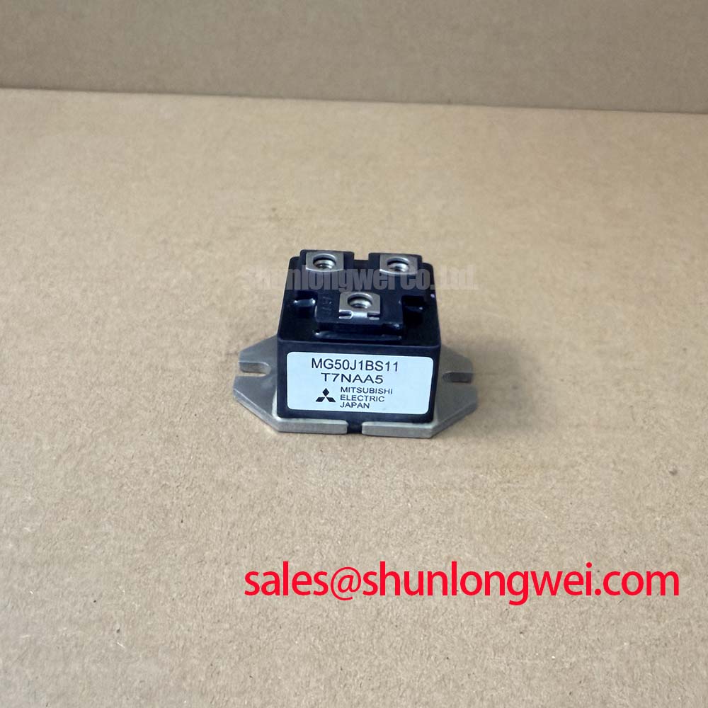
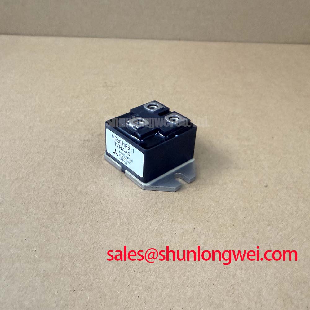
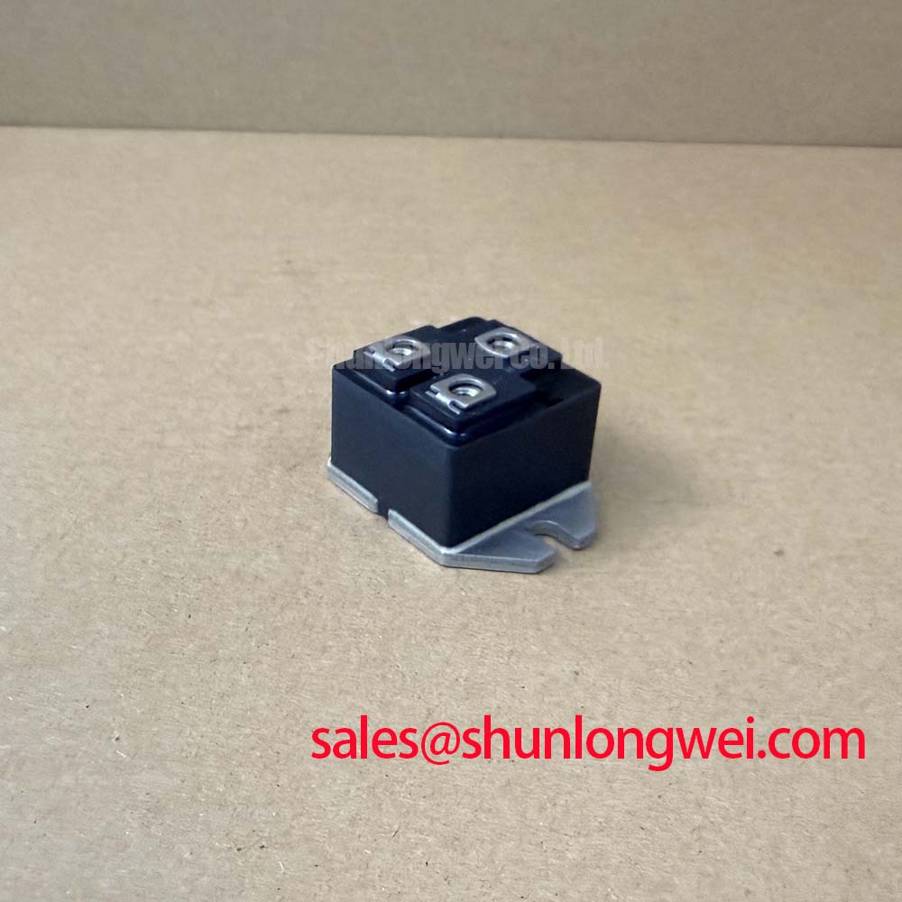
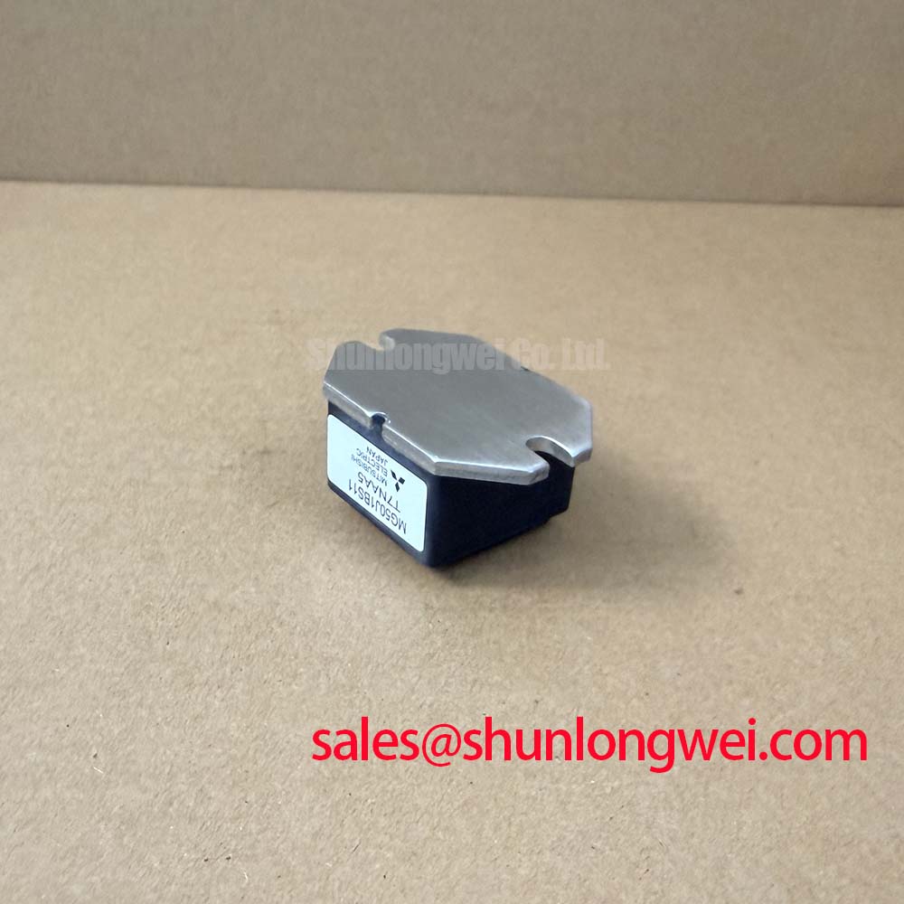
Technical Specifications and Application Insights for the Toshiba MG50J1BS11 IGBT Module
Optimizing thermal overhead in legacy industrial motor controls via a low-saturation, isolated package. Top Specs: 600V | 50A | 0.83°C/W. Key Benefits: Low switching losses reduce cooling footprint; isolated base design simplifies heatsink integration. To address common design concerns: the maximum saturation voltage of 2.7V at 50A collector current ensures minimized conduction losses, keeping device temperatures well below the 150°C limit. For legacy motor drives prioritizing low thermal transient resistance, this 600V module is the optimal choice.
Key Parameter Overview
Decoding the Specs for Enhanced Thermal Reliability
Understanding the electrical boundaries of the MG50J1BS11 helps power electronics engineers establish safe operating margins. The table below lists the essential absolute maximum ratings and electrical characteristics directly extracted from the official manufacturer documentation.
| Parameter | Symbol | Maximum Rating / Value | Unit |
|---|---|---|---|
| Collector-Emitter Voltage | VCES | 600V | V |
| Gate-Emitter Voltage | VGES | ±20V | V |
| Continuous Collector Current (DC) | IC | 50A | A |
| Pulsed Collector Current (1ms) | ICP | 100A | A |
| Collector Power Dissipation (Tc = 25°C) | PC | 150W | W |
| Junction Temperature | Tj | 150°C | °C |
| Collector-Emitter Saturation Voltage (Max) | VCE(sat) | 2.7V | V |
| Thermal Resistance (Junction-to-Case) | Rth(j-c) | 0.83°C/W | °C/W |
| Isolation Voltage (AC, 1 minute) | Visol | 2500V | V |
Download the MG50J1BS11 datasheet for detailed specifications and performance curves.
Application Scenarios & Value
Maximizing System-Level Efficiency in Moderate-Power Motor Drives
Engineers dealing with mid-power motor control units often face the challenge of managing transient heat loads during startup phases. The MG50J1BS11 addresses this issue directly. Its isolated package base prevents leakage current loops between adjacent switches, making it highly suitable for three-phase AC inverter blocks.
In industrial conveyor systems, starting an induction motor demands a sudden current surge. The MG50J1BS11 handles this via its pulsed collector current rating of 100A for 1 ms. This capability prevents peak thermal stress from causing catastrophic latch-up. By integrating this module, designers can reduce gate driver complexity. Its high input impedance permits simpler gate charge transfer networks than traditional bipolar transistors.
Understanding how these components behave is crucial; for a broader view, check out the engineer's ultimate guide to IGBT modules [SLW-content].
For applications requiring higher current handling, the related MG150Q2YS50 offers a collector current rating of 150A under similar voltage conditions, while systems seeking integrated protection logic may look toward the MIG50J7CSB1W intelligent power module. For high-current systems, related offers include the MG400Q2YS60A.
Technical Deep Dive
Analysing the Switching Behavior and Thermal Impedance Matrix
Thermal management dictates the reliability of power modules. Think of thermal resistance like traffic congestion on a bridge. A lower thermal resistance value allows heat to flow smoothly away from the junction. This is similar to traffic moving on an open multi-lane highway. The 0.83°C/W rating of the MG50J1BS11 ensures the module sheds heat efficiently to the heatsink.
The fall time (tf) of 1.0µs represents how quickly the channel can extinguish the current flow. Think of this like turning off a high-pressure water valve. Closing it too slowly causes unnecessary leakage, which translates to higher switching losses in electrical circuits. By ensuring a crisp fall time, the MG50J1BS11 minimizes the heat generated during each switching cycle.
What is the primary benefit of the isolated case design? It simplifies thermal management by eliminating external insulation pads.
How does low saturation voltage improve system performance? It minimizes conduction losses to keep operating temperatures low.
To prevent common degradation pathways, designers should refer to studies on IGBT failure analysis to mitigate overcurrent and overtemperature risks [SLW-content]. In high-power designs, engineers must also consider gate resistance values to balance turn-on times against electromagnetic interference, similar to strategies used by major manufacturers like Mitsubishi. Using proper layout practices, stray inductances in the power loops can be managed effectively. The robust 2-33F1A package provides secure screw terminal connections suitable for industrial environments.
As industrial power architectures shift toward higher efficiency standards, optimizing the performance of legacy systems remains a priority. Modern layouts often integrate newer topologies. However, robust platforms utilizing classic isolated packages continue to serve as stable baselines for industrial drives. The structural characteristics of the MG50J1BS11 offer a predictable solution for engineers balancing design updates with reliable operation.
FAQ
Addressing Key Design and Application Queries
How does the VCE(sat) maximum rating of 2.7V affect the cooling requirements of the MG50J1BS11?
A VCE(sat) of 2.7V at 50A means that at full conduction, the module generates up to 135 Watts of heat. Designers must size their heatsinks using the 0.83°C/W junction-to-case thermal resistance to ensure the junction temperature never exceeds 150°C under load.
What is the engineering benefit of the 2500V AC isolation rating on the case?
The 2500V isolation rating allows multiple MG50J1BS11 modules to be mounted on a single common heatsink without the need for additional ceramic insulating pads. This directly simplifies mechanical assembly and optimizes the thermal dissipation path.
Can this module support high-frequency switching above 20 kHz?
With a fall time of 1.0µs and a turn-off time of 1.6µs, this module is optimized for low-to-medium frequency applications, such as industrial motor drives operating under 15 kHz. High-frequency applications above 20 kHz would experience significant switching losses.
What gate voltage range is recommended to ensure reliable saturation of the MG50J1BS11?
Although the threshold voltage VGE(off) lies between 3.0V and 6.0V, a drive voltage of VGE = +15V is highly recommended to achieve the specified low saturation voltage of 2.7V. A negative gate bias of -5V to -15V during the off-state is recommended to prevent parasitic turn-on in noisy environments.