
Content last revised on October 3, 2026
MG50N2YS1 Circuit Protection and DC Bus Layout
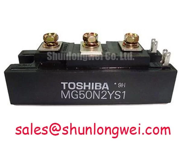
With the drive isolated and its DC bus verified discharged, compare the installed module’s marking and terminal layout with the service documentation before evaluating MG50N2YS1 as a replacement. Toshiba lists this IGBT module with a 1200 V rated voltage, a 50 A rated current, and a Toshiba Module package (Official Specification). Those ratings establish an initial screening boundary; they do not, by themselves, confirm that its terminals, gate drive, thermal interface, or switching behavior match an installed assembly.
Start at the power path rather than the gate resistor. Trace the DC bus from its capacitors through the module connections and back, noting any long conductors, uneven current paths, or service changes to the original busbar. As a Design Consideration, reducing loop inductance can limit the voltage added to the DC bus during current interruption. The relevant check is the collector voltage at turn off under the intended operating conditions, measured with a probe and technique appropriate to the circuit. Compare the observed peak with the module’s 1200 V rated voltage (Official Specification); a bus voltage reading alone will not reveal the switching overshoot.
A laminated or closely coupled busbar can be evaluated where the equipment layout permits it, but no busbar inductance target or snubber value is an MG50N2YS1 factory specification here. If a snubber is already fitted, inspect its connections and condition against the equipment schematic before changing its components. Snubber selection is a system design decision informed by measured waveforms, switching losses, and the available voltage margin. Keep physical clearance and creepage decisions tied to the equipment’s applicable insulation requirements rather than inferring them from the module’s voltage rating.
For a heavy-duty variable frequency AC motor drive, the module may be assessed as part of an inverter repair, subject to confirmation of the installed circuit and mechanical fit. The rest of that drive’s power path must be checked independently. For example, MG150Q1JS40 is another module a maintenance team might encounter while reviewing the wider power assembly; its function or interchangeability in a particular drive cannot be inferred from the MG50N2YS1 rating.
If the recorded collector waveform shows an unexpected peak, compare it with a known-good phase or an earlier commissioning record before assigning a cause. Probe placement, busbar connections, snubber condition, and gate timing all warrant examination. A repeated measurement at controlled operating conditions is more useful than treating one captured spike as a definitive diagnosis.
Field Diagnostics and Dynamic Gate Impedance
Inspect the installed gate-drive schematic before energizing a replacement MG50N2YS1. Confirm the gate and emitter connections from the original documentation, then check the continuity of the external drive path with power removed. During controlled commissioning, observe gate-to-emitter voltage at the module terminals alongside collector voltage and current. This helps distinguish a drive-command problem from a disturbance appearing during the opposite switch’s transition.
Rapid voltage change in a switching leg can couple into an off-state gate path. As a Design Consideration, a low-impedance turn-off path or an active Miller clamp may help resist an unintended gate-voltage rise, but its suitability depends on the existing driver and measured behavior. Negative off-bias is likewise a driver-level choice, not a stated MG50N2YS1 requirement. The discussion in Evolution of Negative Off-Bias Gate Drive Circuits provides context for evaluating that choice without assigning an unsupported bias setting to this module.
💡 Pro Tip: Check turn-off voltage at the module terminals under a controlled switching test before changing the gate network, because a waveform measured only at the driver can miss disturbances along the connection.
When investigating apparent cross-conduction, compare command signals, actual gate waveforms, and current behavior in the same switching interval. An abnormal current trace does not identify a single failed part: timing, drive-path impedance, measurement setup, and the opposing switch should all be reviewed. Changes to gate impedance should be verified against both turn-on behavior and turn-off voltage stress rather than judged solely by whether one symptom disappears.
Parallel operation calls for additional caution. The supplied MG50N2YS1 specifications do not establish a collector-emitter saturation-voltage temperature characteristic or guarantee static current sharing. If modules are paralleled in an existing assembly, designers should check the applicable Toshiba characteristic data and measure branch currents under representative conditions. Symmetry in busbar and gate-drive connections is a useful Design Consideration, but it does not replace current-sharing verification.
In a repair review, MG100Q1ZS40 can be recorded as a separate candidate for comparison, not an assumed drop-in substitute. Its electrical ratings, terminal arrangement, drive requirements, and mounting interface must be compared with both the installed part and the equipment documentation before any substitution decision.
Field Diagnostics and Gate-Drive Isolation
Separate the question of whether the power module fits from whether the equipment’s isolated gate-drive system remains suitable. Identify the driver supply, control-signal barrier, and fault-reporting path on the actual drive schematic. Then inspect connectors and wiring for damage or routing changes before measuring signals. The MG50N2YS1 voltage and current ratings do not specify a reinforced isolation rating or common-mode transient immunity for an external driver.
As a Design Consideration, fast switching can disturb a driver across its isolation barrier or through shared wiring. If an unexpected gate pulse appears, capture the control command and gate-to-emitter waveform together, using measurement equipment suitable for the circuit’s potential. Compare the event with a known-good channel where possible. Such a pulse may point toward coupling, supply disturbance, or a timing issue; it is not proof that the isolation barrier has failed.
Driver isolation ratings, clearance, and creepage must be verified from the selected driver and the equipment’s governing requirements. They cannot be assigned to this Toshiba module by association. If the drive uses fault feedback to inhibit switching, confirm that the reported event and the measured gate behavior agree before replacing hardware. This keeps the investigation anchored to the installed system rather than an assumed driver specification.
Motor-control method also affects which waveforms are most useful to capture. Direct torque control is one control approach that can produce changing switching demands, while the Clarke transformation is used in analyzing three-phase motor quantities. Neither establishes a gate-driver rating for MG50N2YS1; the equipment schematic and measurements determine the relevant commissioning checks.
Benchtop Waveform Tuning and Thermal Stress
Before a pulsed-load test, confirm how the installed module contacts its heatsink and where the equipment senses temperature. Check the mounting surface and the applicable assembly instructions rather than assuming a torque or interface-material thickness from the Toshiba Module package description. After mounting, establish a repeatable test condition and record current, switching waveforms, and the available case or heatsink temperature measurement together.
The 50 A rated current (Official Specification) is an important screening figure, but it is not a standalone allowance for every overload pulse. Peak junction temperature depends on losses, pulse duration, starting temperature, and the thermal path. A transient thermal calculation would require applicable Toshiba thermal-impedance and loss data, which are not included in the supplied specifications. Without those inputs, a numerical junction-temperature margin would imply precision the available data cannot support.
As a Design Consideration, review conduction and switching stress together when tuning a drive. A gate-network change that alters switching speed can change both the collector-voltage peak and dissipated energy. Capture waveforms under controlled conditions and compare them with the equipment’s previous records or a known-good phase. If the case-temperature trend changes while electrical loading appears similar, inspect heatsink contact and airflow as well as the measurement location; the trend alone does not establish a cause.
For an MG50N2YS1 integration decision, retain the measured waveforms, thermal test conditions, and the exact Toshiba characteristic data used for the review. That record lets the system engineer assess the 1200 V and 50 A official ratings against the drive’s observed electrical and thermal demands without treating a nominal rating as proof of application-level margin.