

Content last revised on October 2, 2026
Preventing Spurious Faults: Active Miller Clamp Implementation Guidelines for MIG150Q6CMB1X
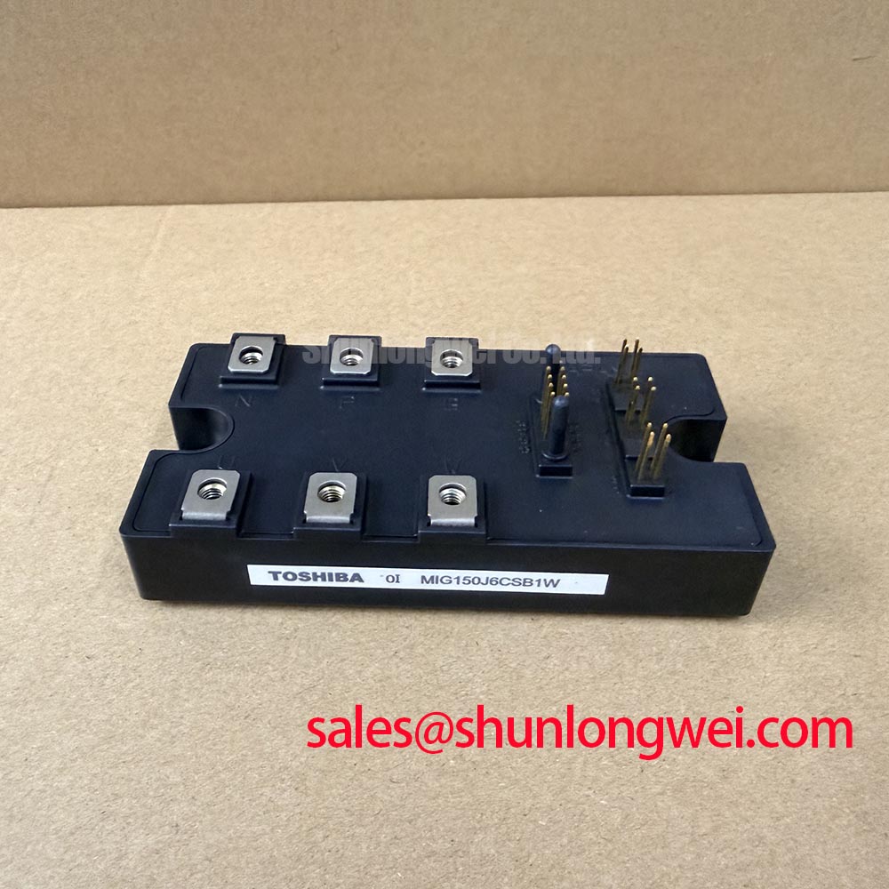
During a fast commutation event, voltage movement at the power terminals can couple through the device’s internal gate capacitances and disturb a neighbouring gate circuit. A possible result is an unintended gate excursion or cross-conduction in the converter leg. This is a system-level switching behaviour, not an additional official rating of the MIG150Q6CMB1X. The practical objective is to keep the gate control path quiet while the opposite device is changing state.
An active Miller clamp can be considered when the selected gate driver provides a dedicated clamp function. The clamp path should be physically close to the relevant gate and emitter connections, with a short return path that does not share high-current commutation copper. The driver supplier’s permitted gate voltage, clamp-current capability, propagation behaviour, and undervoltage response must be checked against the Toshiba device documentation and the complete power-stage layout.
Negative gate bias is also a possible design option in applications where the switching environment creates a credible risk of false turn-on. The exact negative value must be selected by the system designer after checking the module’s gate-emitter absolute maximum limits, driver capability, start-up sequencing, and fault behaviour. The supplied product data does not establish a negative gate-bias value for this model, so a fixed setting should not be presented as a universal requirement.
For commissioning, first disconnect the DC link and verify the gate-driver output at the module connector. Then check the gate-to-emitter waveform with a measurement method suitable for high common-mode switching. Compare the idle, turn-on, turn-off, and fault states with the known-good signal path. An unexpected pulse may involve driver timing, probe reference error, common impedance, parasitic coupling, or a damaged power device; the oscilloscope record should be reviewed before assigning a single cause.
Gate-loop geometry should minimise shared inductance and avoid routing a sensitive gate trace beside the collector or emitter commutation path for extended distances. Clearance and creepage must be selected according to the working voltage, pollution environment, insulation system, and applicable equipment standard. The Precision Gate Drive Design reference can be used as a related engineering resource, while final spacing and protection decisions remain part of the equipment design.
For a repair comparison, MG150Q1JS40 may be reviewed as a separate Toshiba product reference, but its electrical configuration, terminal arrangement, ratings, and switching characteristics must be checked independently. Similar-looking module dimensions do not establish interchangeability.
Field Diagnostics & Commissioning: Cosmic Ray Robustness and Voltage Derating in MIG150Q6CMB1X Topologies
Terrestrial radiation effects and single-event failure mechanisms can become part of a high-voltage reliability assessment, especially where equipment operates at elevated altitude or with limited DC-link margin. The supplied product information does not provide a FIT rate, single-event burnout rating, neutron test result, altitude derating curve, or guaranteed operating lifetime for the MIG150Q6CMB1X. No numerical field failure rate or service-life prediction should therefore be assigned to this device from its voltage and current ratings alone.
A responsible commissioning review begins with the highest measured DC-link voltage, switching overshoot, operating temperature, load profile, and fault-clearing time. Record these conditions during representative switching tests and compare the measured peak stress with the applicable Toshiba limits. If the equipment is installed above its original design altitude, the system engineer should reassess cooling performance, insulation coordination, creepage requirements, and available electrical headroom using the relevant equipment standard or manufacturer reliability data.
Voltage derating is a design consideration rather than a fixed percentage that can be stated for every installation. The suitable margin depends on bus transients, clamp behaviour, temperature, repetitive switching stress, layout inductance, and protection response. A field diagnosis that shows repeated high-voltage faults should include a review of the DC-link charging circuit, braking or clamp network, gate timing, load regeneration, and oscilloscope traces taken at the module terminals.
Thermal interface installation also requires controlled workmanship. Clean both mating surfaces, apply only the interface material specified by the equipment or heatsink procedure, and prevent voids, contamination, and uneven compression. The supplied information does not confirm a universal interface thickness or mounting torque for this model. Use the module’s mechanical documentation and the heatsink manufacturer’s procedure rather than transferring values from another package.
⚠️ Field Alert: Never insert or remove the module connector, gate lead, or measurement accessory while the DC link or an auxiliary gate supply remains energised.
During a suspected radiation-related or high-voltage event, inspect the external evidence before replacing the module. Measure the isolated bus, check the clamp components, review gate resistance and driver supply behaviour, and compare cold-state terminal responses with the reference unit. A short circuit observed after an event may be associated with electrical overstress, thermal conditions, gate-drive malfunction, or mechanical installation problems; a laboratory failure analysis is required to separate these possibilities.
In a converter that uses a staged supply, the upstream rectification or auxiliary power section should be evaluated as part of the same fault path. The MG75H6EL1 can be consulted as a separate product reference for topology-level comparison, but it should not be treated as an automatic companion or replacement for the Toshiba module.
Assembly Integrity & Layout Architecture: Implementing Planar Symmetrical Busbar Geometry for MIG150Q6CMB1X
Power-loop construction has a direct influence on the voltage seen by the switching device. In practical terms, the turn-off peak rises with DC-link voltage and with the product of stray inductance and current-change rate. This relationship explains why two assemblies using the same 1200.0 V module can show different oscilloscope peaks. The correct target is established by the system engineer after measuring the real converter under the intended load and switching conditions.
A planar busbar arrangement can help reduce loop area when the positive and negative paths are placed close together and the commutation path is kept compact. The capacitor location, module terminal geometry, laminated conductor construction, fastener clearance, insulation barriers, and probe attachment point all influence the measured result. Avoid extending the high-current path simply to make the mechanical assembly easier; verify the resulting overshoot at the module terminals, not only at a remote DC-link capacitor.
Snubber selection should follow measured ringing rather than a generic capacitor value. First identify the ringing frequency, damping behaviour, energy requirement, capacitor voltage stress, pulse-current capability, and resistor losses. Then validate the chosen network during normal switching, overload response, and turn-off fault conditions. A snubber that suppresses one waveform can add loss or create a different transient if its parasitic inductance and placement are not included in the test.
Symmetry is useful when the topology contains parallel current paths or multiple switching positions. Match conductor length and contact geometry where the circuit requires balanced current sharing, and keep control references separate from high-current return paths. The module’s official package classification does not provide a universal busbar dimension, clearance value, or inductance limit. Those values must be calculated and verified for the assembled equipment.
Mechanical inspection should include flatness of the heatsink contact area, correct washer and insulator placement, even fastener engagement, and the absence of stress on the module base or terminals. Tightening sequence and torque are installation-process requirements governed by the relevant mechanical documentation. After assembly, perform an insulation check only with a test level approved for the complete equipment and compatible with connected driver, sensor, and suppression circuits.
If the measured turn-off peak changes substantially after replacing a capacitor, busbar, or mounting arrangement, retain both waveforms in the service record. This comparison can reveal whether the dominant issue is electrical topology, measurement technique, device timing, or mechanical rework. It is more useful than assuming that the module alone determines the transient response.
Transient Dynamics & Electrical Design: Reinforced Insulation Barrier Integrity on MIG150Q6CMB1X
The MIG150Q6CMB1X is a power module, not an independent declaration of reinforced system insulation, common-mode transient immunity, or EMC compliance. The complete inverter welder or induction-heating supply must provide the required galvanic isolation between control electronics, gate drivers, power terminals, heatsink structures, and accessible conductive parts. The supplied product data does not confirm a specific reinforced isolation rating or CMTI value for this module, so those figures must not be assigned to it.
When reviewing an isolated gate-drive arrangement, verify the isolation component’s certified working voltage, impulse withstand capability, creepage and clearance, insulation type, common-mode transient behaviour, and temperature limits. The PCB layout should maintain the barrier through every layer, cutout, connector, mounting feature, and test point. Copper pours and measurement pads placed near the barrier can reduce the effective spacing even when the top-layer drawing appears acceptable.
Spurious gate pulses during a high-voltage transition may result from insufficient isolation performance, common reference movement, driver supply disturbance, capacitive coupling, probe error, or an incorrectly sequenced control signal. Commissioning should therefore monitor the isolated primary-side and secondary-side supplies, driver input, driver output, and gate-to-emitter waveform with suitable differential measurement equipment. Compare the timing during normal switching and during the equipment’s defined fault response.
Power-up and power-down sequencing should be treated as a system requirement. The control board should prevent an undefined driver state while the power stage is charging, and the gate output should remain within the permitted device range throughout supply undervoltage and fault recovery. The required thresholds and delays depend on the selected driver and control architecture; they are not established by the three product parameters supplied for this Toshiba module.
Topology review can also benefit from neutral industry references such as Solar Inverter Topologies and Grid-Tied Systems for power-conversion arrangements and Droop Control for Parallel Inverter Operation in AC Microgrids for parallel-operation concepts. These references do not certify the MIG150Q6CMB1X or establish its application limits. Final acceptance should be based on the Toshiba documentation, the equipment standard, measured switching waveforms, and the completed insulation test plan.