Content last revised on September 28, 2026
Transient Dynamics and Electrical Design for MIG15J805H
Gate-voltage disturbances deserve attention when evaluating the MIG15J805H in a switching assembly. A fast voltage change at a power terminal can couple through a device’s feedback capacitance into its gate-control path. If the off-state path cannot hold the gate at its intended potential, unintended turn-on is possible. This is a Design Consideration, not a claim that a particular disturbance level or internal clamp has been specified for this module.
Start with the existing drive-board schematic and the original equipment documentation. Identify how the board establishes the off state, where its gate-current return flows, and whether any active Miller clamp or negative off-bias arrangement belongs to the surrounding drive circuit. Do not assume that a gate terminal, clamp connection, or protection function is externally accessible on this intelligent power module. The discussion in Evolution of Negative Off-Bias Gate Drive Circuits provides background for assessing an off-bias strategy; the actual bias and drive limits must come from the applicable module and equipment documentation.
For a live switching investigation, use measurement techniques and probes rated for the circuit, then compare off-state control waveforms with the switching-node transition and the fault indication. A coincident disturbance may warrant checking the drive return path, connector contact, local decoupling, and board layout before changing drive components. Pro Tip: Keep the drive and return paths closely coupled where the equipment layout permits, then verify the off-state waveform during switching rather than treating a quiet static measurement as proof of immunity.
Clearance between the power circuit and accessible control circuitry must be assessed in the context of the complete assembly. Safety Extra Low Voltage (SELV) and PELV electrical safety explains the distinction between low-voltage circuit arrangements; it does not certify the MIG15J805H or establish the insulation design of equipment containing it. The equipment designer should verify isolation boundaries and applicable safety requirements separately.
Benchtop Waveform Tuning and Connected-Load Stress
When a repaired drive shows abnormal terminal ringing, measure at both the module-side connection and the relevant load-side connection before assigning the cause to the MIG15J805H. Cable length, load impedance, output filtering, probe placement, and the return path can all affect the observed waveform. A reflected-voltage pattern may indicate a cable and load impedance issue, but its magnitude cannot be inferred from the module’s 600 V rating alone. Record the DC-link condition and operating state alongside each waveform so comparisons remain meaningful.
An output choke or dv/dt filter is a system-level design choice, not an inherent requirement established by the supplied module specifications. If an existing industrial inverter welder or medium-frequency induction-heating supply uses either component, compare its installed configuration with the equipment drawings before substituting parts. Those equipment types are potential compatibility-evaluation contexts only; the 15 A module rating does not establish that the MIG15J805H is suitable for a particular welder or heating supply.
At the bench, distinguish repetitive switching stress from a fault event. Capture the switching-node waveform with an appropriate differential measurement method, inspect the DC-link connections, and check whether ringing changes with the connected cable or load. If a high-speed semiconductor fuse forms part of the equipment protection scheme, its clearing behavior needs evaluation against the complete circuit’s fault current and the device limits stated in the applicable manufacturer documentation. The voltage and current ratings given here do not provide a surge-current limit, short-circuit withstand time, or fuse coordination value.
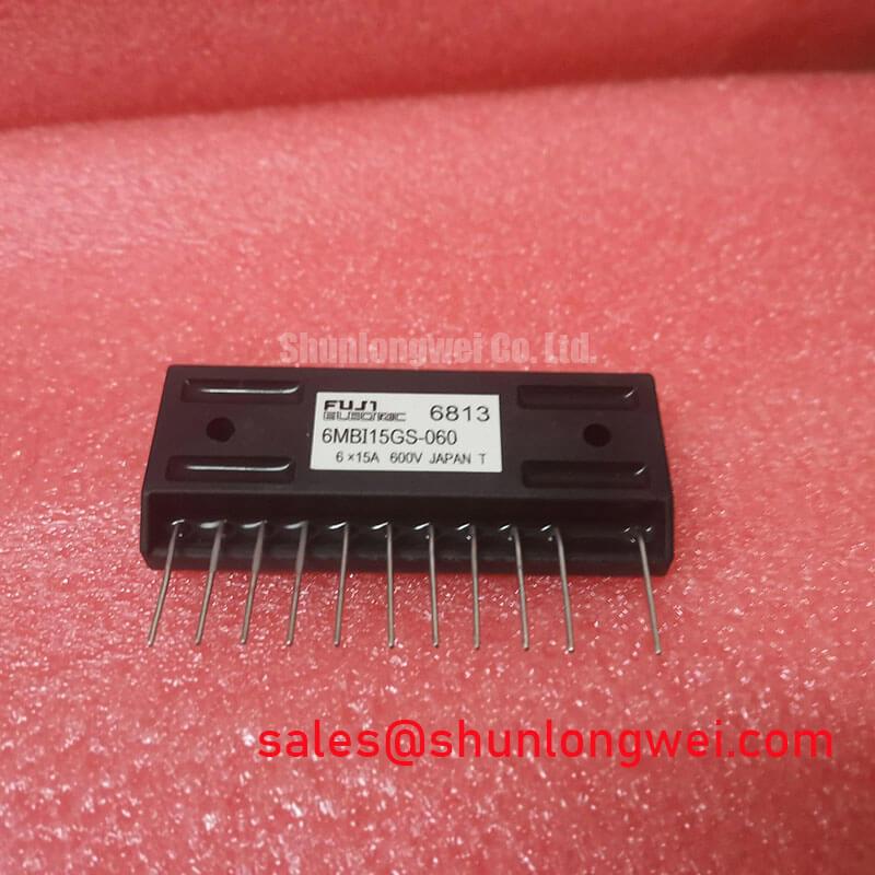
A proposed replacement should be compared by documented electrical behavior and physical interface, not by headline voltage and current figures alone. The 6MBI15L-060 is a separate product to place on a comparison worksheet; no pin compatibility or drop-in equivalence is implied. Check the original drawings for terminal assignment, control requirements, mounting interface, thermal path, and protection behavior before any substitution assessment.
MIG15J805H Circuit Protection and Fault-Clearing Behavior
If the equipment reports a short-circuit or overcurrent fault, preserve the fault record before resetting it. Compare the command signal, available fault output, DC-link behavior, and measured current using the equipment’s service procedure. A fault indication alone does not identify a failed MIG15J805H: load wiring, current sensing, drive supply behavior, and the protection circuit may each require examination.
Desaturation detection and controlled turn-off are common subjects in power-stage protection design, but their implementation cannot be assigned to this model from the stated 600 V and 15 A specifications. In particular, no detection time, short-circuit safe operating area, or two-stage turn-off sequence is established by those figures. When assessing a drive board that implements such functions, trace its documented fault path and measure the interval from fault onset to current reduction under an approved test procedure. The acceptance limit must come from the relevant Toshiba documentation and the equipment design, not from a generic timing target.
Fault interruption can itself produce an inductive voltage rise. As a Design Consideration, review the local DC-link path, snubber connections, and current-loop geometry so a protection event does not move the module terminal voltage outside its documented limits. A snubber value cannot be selected responsibly from the module’s voltage rating alone: the system engineer needs the circuit impedance, switching waveform, energy to be managed, and component ratings.
Control-board isolation also merits a measurement-led check where faults coincide with switching edges. Compare the drive-board supply and isolator signals during the event, then evaluate common-mode transient immunity against the isolator manufacturer’s documentation. This does not imply a particular optocoupler, digital isolator, or internal isolation structure in the MIG15J805H.
Field Diagnostics and Commissioning of the Power Loop
Before re-energizing an assembly, inspect the module seating, terminal hardware, busbar contact surfaces, and nearby decoupling connections against the equipment drawings. A symmetrical, closely coupled outgoing and return power path is a useful Design Consideration because it can reduce the loop inductance that contributes to turn-off overshoot. The attainable geometry and acceptable peak voltage remain system-dependent; neither a busbar inductance target nor a snubber size follows from the confirmed module ratings.
During commissioning, capture the DC-link voltage and the peak module-terminal voltage under the operating conditions authorized by the equipment procedure. The difference between them can grow as loop inductance and current slew rate increase. Compare the measured peak with the applicable device limits while also checking probe bandwidth, grounding, and measurement location. If the result changes after busbar or decoupling work, repeat the measurement at comparable current and DC-link conditions before attributing the change to the module.
Field Alert: Do not disconnect module or load cabling until the equipment is isolated and the DC link has been verified discharged.
If commissioning reveals intermittent trips, work from the recorded waveform back through the connections rather than replacing multiple parts at once. Check terminal tightness using the equipment manufacturer’s procedure, inspect the drive connector and fault-signal path, and compare cold-state measurements with a documented known-good assembly where one is available. For operation in an environment with unusual altitude, temperature, or insulation demands, request the applicable manufacturer and equipment limits; the available 600 V and 15 A figures do not establish a derating curve, service-life estimate, or insulation-reliability claim.