


Content last revised on April 14, 2026
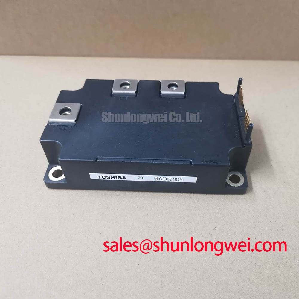
Toshiba MIG200Q101H 1200V/200A IGBT Module: Technical Data for High-Efficiency Motor Drives
The Toshiba MIG200Q101H is a 1200V, 200A 6-pack IGBT module engineered to reduce conduction losses and enhance the efficiency of industrial inverter systems. This H-Series intelligent power module integrates a three-phase bridge in a single, compact package, offering key specifications of 1200V | 200A | VCE(sat) 2.7V (Max). The primary engineering benefits include a lower thermal load on the overall system and a significantly simplified design and assembly process. It directly addresses the core engineering challenge of balancing high power output with thermal efficiency by providing a low collector-emitter saturation voltage in a highly integrated form factor.
Key Parameter Overview
Decoding the Specs for Reduced Conduction Losses
The technical specifications of the MIG200Q101H are optimized for robust performance in high-power switching applications. The parameters listed below are critical for calculating system efficiency, thermal management strategies, and ensuring operational reliability. Particular attention should be paid to the low VCE(sat) value, a key determinant of conduction losses.
| Parameter | Symbol | Conditions | Value | Unit |
|---|---|---|---|---|
| Collector-Emitter Voltage | VCES | VGE = 0V | 1200 | V |
| Gate-Emitter Voltage | VGES | ±20 | V | |
| Collector Current (DC) | IC | Tc = 25°C | 200 | A |
| Collector Current (Pulse) | ICP | Tc = 25°C, 1ms | 400 | A |
| Collector-Emitter Saturation Voltage | VCE(sat) | VGE = 15V, IC = 200A, Tj = 25°C | 2.7 (Max) | V |
| Diode Forward Voltage | VF | -IC = 200A, VGE = 0V | 2.6 (Max) | V |
| Total Power Dissipation | PC | Tc = 25°C | 1040 | W |
| Operating Junction Temperature | Tj | -40 to +150 | °C | |
| Thermal Resistance (Junction-to-Case, IGBT) | Rth(j-c) | Per Arm | 0.12 (Max) | °C/W |
| Isolation Voltage | Visol | AC, 1 minute | 2500 | Vrms |
Download the MIG200Q101H datasheet for detailed specifications and performance curves.
Application Scenarios & Value
Achieving System-Level Benefits in Industrial Motor Control
For systems engineers designing industrial power conversion systems, such as a Variable Frequency Drive (VFD) for factory automation, the MIG200Q101H provides a direct path to a more compact and efficient solution. The primary challenge in these applications is managing the waste heat generated during operation, which dictates the size of the heatsink and the overall enclosure volume. The MIG200Q101H's low VCE(sat) of 2.7V at its nominal 200A current rating is a critical advantage. This parameter directly minimizes conduction losses—the primary source of heat in high-current, moderate-frequency applications—leading to a reduced thermal burden and enabling a smaller, more cost-effective heatsink design.
This module is ideally suited for:
- Industrial Motor Drives: Providing precise and efficient control for AC induction motors in applications like conveyors, pumps, and fans.
- Servo Drives: Delivering the high current and controlled switching necessary for high-performance robotics and CNC machinery.
- Welding Power Supplies: Offering a robust switching stage capable of handling the high-current demands of industrial welding equipment.
- Uninterruptible Power Supplies (UPS): Forming the core of the inverter stage in high-power UPS systems, ensuring reliable power backup.
By integrating six IGBTs and six freewheeling diodes into one module, the MIG200Q101H also reduces assembly complexity and minimizes stray inductance compared to a discrete component solution, further enhancing system reliability. For systems requiring higher power handling, the related CM400HA-24H offers a collector current of 400A.
Technical Deep Dive
A Closer Look at Conduction Loss and Its System-Level Impact
The collector-emitter saturation voltage, or VCE(sat), is a fundamental parameter that defines an IGBT's on-state efficiency. It represents the voltage drop across the device when it is fully turned on and conducting current. This voltage drop, when multiplied by the current flowing through it, results in power loss in the form of heat (P_loss = VCE(sat) * IC). The MIG200Q101H's specification of 2.7V maximum at 200A is central to its value proposition. A lower VCE(sat) means less power is wasted as heat during each conduction phase of the Pulse Width Modulation (PWM) cycle, directly improving the inverter's overall efficiency. Think of VCE(sat) as the electrical "friction" of the switch; lower friction means more of the input power is delivered to the load—in this case, the motor—and less energy is diverted into heating the component. This reduction in waste heat allows engineers to design more compact cooling systems, ultimately enabling higher power density for the entire drive.
Frequently Asked Questions (FAQ)
What is the primary significance of the 2.7V maximum VCE(sat) on the MIG200Q101H?
A low VCE(sat) is critical for minimizing power loss during the IGBT's on-state. This directly translates to lower heat generation, which improves overall system efficiency and allows for smaller, more cost-effective thermal management solutions like heatsinks.
How does the integrated 6-pack configuration of the MIG200Q101H benefit a power electronics design?
The 6-in-1 package simplifies the design of three-phase inverters by replacing multiple discrete components. This reduces assembly time, lowers component count on the PCB, and minimizes parasitic inductance between switches, which can improve switching performance and reduce voltage overshoots.
Is the MIG200Q101H suitable for applications with high switching frequencies?
The datasheet specifies turn-on and turn-off times (ton, toff) of 1.5µs and 2.0µs respectively. While suitable for typical motor control frequencies (up to ~15-20 kHz), engineers must carefully evaluate the trade-off between switching frequency and switching losses. For an in-depth analysis, refer to our guide on decoding IGBT datasheets.
What is the purpose of the built-in free-wheeling diodes (FWD) in this module?
The co-packaged FWDs are essential for inductive loads like motors. When an IGBT turns off, the energy stored in the motor's inductance must have a path to flow. The FWD provides this path, preventing a large voltage spike across the IGBT that could otherwise cause damage. Their performance is crucial for the reliability of the inverter.
The strategic selection of an IGBT Module like the MIG200Q101H, with its focus on low conduction losses and high integration, provides a solid foundation for developing power conversion systems that are not only powerful but also efficient and reliable over their operational lifespan. This enables designers to meet increasingly stringent energy standards and market demands for more compact industrial equipment.