Content last revised on September 30, 2026
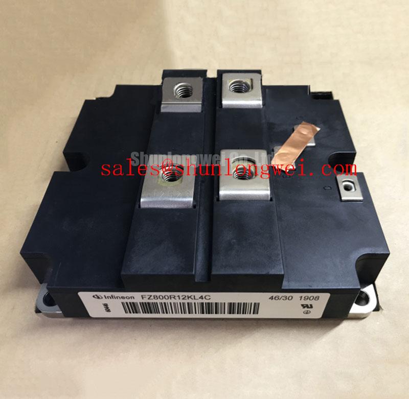
MMF800Y020DK1 MacMic 1200 V 800 A IGBT Module
Before energizing a replacement, isolate the module, apply ESD controls, and record the cold-state resistance and diode-test readings between the identified power terminals and gate terminals. Confirm the markings, terminal polarity, mounting condition, and equipment bus rating against the original assembly documentation.
| Parameter | Official Specification | Engineering Meaning |
|---|---|---|
| Collector emitter voltage, VCES | 1200 V | Maximum stated collector emitter blocking voltage. |
| Continuous collector current, IC, at TC = 80 °C | 800 A | Specified continuous current capability at the stated case temperature. |
| Turn off switching loss, Eoff, at Tj = 125 °C | 175 mJ typical | Typical energy dissipated during the turn off transition under the specified test conditions. |
| Junction to case thermal resistance per IGBT | 0.05 °C/W maximum | Thermal path characteristic used when evaluating the cooling assembly. |
| Operating junction temperature | −40 °C to +150 °C | Specified operating junction temperature range. |
These are official specification values supplied for MMF800Y020DK1 by MacMic. They do not, by themselves, establish a complete inverter rating. The system engineer should verify switching frequency, DC link voltage, current waveform, cooling performance, gate drive conditions, overload behavior, and the applicable protection settings.
💡 Bench Tip: Keep the gate terminals shorted to the emitter reference during incoming inspection, use an ESD controlled workstation, and compare diode mode results with a known good unit rather than treating one meter reading as a complete pass or fail decision.
Field Diagnostics and Commissioning for Common Mode Transients
For a commercial string inverter or microgrid energy storage converter, begin commissioning with the power stage de energized and trace the actual gate return path from the driver board to the module. The provided product data confirms voltage, current, switching loss, thermal resistance, and junction temperature ratings, but it does not confirm a reinforced isolation voltage or a common mode transient immunity value. Any requirement such as isolation above 5 kV or CMTI above 100 kV/µs must therefore be verified from the applicable driver, isolation barrier, and system test documentation rather than assigned to the IGBT module.
As a Design Consideration, inspect creepage and clearance around the isolated gate drive interface, keep high dv/dt power nodes away from signal references, and verify the isolation barrier under the actual mechanical contamination and enclosure conditions. During troubleshooting, monitor the gate emitter waveform at the module terminals with suitable probing technique. A brief gate disturbance may indicate coupling, probing error, inadequate return routing, or driver instability; compare it with the known good phase and review the switching event at the same time.
Turn Off Switching Loss and Inductive Overshoot Evaluation
The official Eoff value of 175 mJ typical at Tj = 125 °C is a test condition, not a universal system loss value. Actual loss changes with current, gate resistance, DC link voltage, junction temperature, commutation behavior, and the freewheel diode characteristics in the switching path. When commissioning, capture collector emitter voltage and current together so the engineering team can compare turn off energy and peak voltage with the converter’s verified operating limits.
Turn off overshoot is governed by the DC link voltage plus the voltage developed across stray inductance during current change. The practical response is to minimize the high current commutation loop, use a symmetrical laminated or planar bus structure where appropriate, and validate the selected snubber through measured switching waveforms. Do not assume a specific inductance limit or capacitor value without the complete topology and test data. Parallel module operation also requires symmetrical electrical paths and thermal conditions; current sharing should be confirmed through measured collector current and junction temperature behavior rather than inferred from the nominal 800 A rating.
The reverse recovery softness of the associated freewheel diode can influence voltage overshoot, ringing, and radiated EMI. Since no softness factor is supplied here, the integrator should obtain the relevant diode switching curves for the complete assembly. The PTFE material reference from this technical resource may assist material and dielectric discussions, but it does not verify the construction or insulation performance of this MacMic module.
Dynamic Gate Impedance Checks for Spurious Faults
Before applying a high voltage bus, check gate-emitter resistance, driver supply sequencing, interlock operation, and the dead time implemented by the inverter controller. The product information supplied for MMF800Y020DK1 does not specify a gate voltage range, active Miller clamp requirement, or negative gate bias value. Those settings must be taken from the applicable MacMic gate drive documentation and validated against the actual driver circuit.
As an Engineering Recommendation, keep the gate loop compact, place the gate resistor and any clamp components close to the module interface, and separate the power commutation path from the control return. A high dv/dt event accompanied by an unwanted gate pulse may involve parasitic coupling, common emitter inductance, driver saturation, insufficient dead time, or measurement disturbance. Verify both complementary switch waveforms with isolated, low inductance probing before changing the gate network.
For a possible direct replacement evaluation, engineers may compare the electrical interface, mechanical arrangement, thermal path, and gate requirements with FZ800R12KS4_B2. This is a neutral reference for comparison, not a blanket substitution recommendation. The original equipment documentation remains the authority for pin compatibility and operating conditions.
PCB Gate Loop Symmetry and Thermal Commissioning
Route the auxiliary emitter or control return independently from the main high current emitter path wherever the module interface provides that distinction. The objective is to prevent load current voltage drop and shared inductance from appearing in the gate drive reference. Designers should verify the gate emitter waveform directly at the module terminals, then compare both switching directions and all parallel phase paths for ringing, delay, and unequal amplitude.
Thermal commissioning should use the stated 0.05 °C/W maximum junction to case thermal resistance per IGBT together with the real heatsink, interface material, mounting pressure, airflow, and switching loss. The −40 °C to +150 °C operating junction range is an official boundary, not a permission to operate at the limit continuously without thermal analysis. For pulsed operation, the system team should evaluate transient thermal impedance and peak junction temperature using the actual pulse profile.
⚠️ Field Alert: Disconnect the DC link and verify the absence of hazardous voltage before inserting, removing, or probing the gate drive connector.
Long motor or converter cables can behave as transmission paths, producing reflected voltage at the load and inverter terminals. If a field waveform shows a double peak or ringing, check cable length, termination behavior, switching edge rate, grounding, and probe placement before attributing the condition to the module. A measured gate loop and power loop comparison usually provides more useful evidence than a resistance check alone.
For broader power semiconductor technology context during reliability planning, consult the Wide Bandgap Revolution reference. It should be treated as background engineering material; it does not replace the MacMic product data or the converter manufacturer’s qualification requirements.