Content last revised on October 15, 2026
Field Diagnostics & Commissioning: Coordination of Primary Spark Gaps, MOVs, in MP508 Topologies
Trace each surge-protection device to its actual connection point before assessing protection of the MP508. As a Design Consideration, a primary spark gap, an MOV, and an RC suppression network perform different functions: their coordination depends on the incoming supply, source impedance, protective-device characteristics, and wiring between the protection stage and bridge.
The relevant surge-immunity reference is IEC 61000-4-5, rather than “IEEE 61000-4-5.” An equipment-level surge test does not establish an independent immunity certification for this rectifier. The National Electrical Manufacturers Association provides standards resources for electrical equipment; the applicable equipment standard and test configuration must govern the finished assembly.
For voltage assessment, compare the reverse stress at the bridge with its 800 V official specification, including supply tolerance and measured transient behavior. A nominal AC supply designation alone does not establish adequate surge margin. MOV residual voltage, connection inductance, and surge current all influence the stress reaching the rectifier.
For fuse coordination, use the fuse manufacturer’s total-clearing I²t characteristics together with the semiconductor’s applicable surge withstand data. The 400 A official surge rating is not a repetitive charging-current allowance or, by itself, a fuse-selection criterion. Its waveform, duration, and initial thermal conditions matter. During commissioning, capture capacitor-charging current and inspect the precharge circuit before attributing repeated fuse operation to the bridge.
MP508 Operational Boundaries: Preventing Localized Thermal Damage
Exclude gate-firing adjustments from the MP508 diagnostic procedure: this diode bridge has no gate input, holding-current setting, firing-pulse rise-time requirement, or back-porch drive interval. Gate hotspot analysis, Miller-charge control, and active gate clamping belong to other semiconductor types, not this rectifier.
The relevant thermal concern is forward-conduction heating and its removal through the installed assembly. As a Design Consideration, evaluate the operating current against the mounting and cooling conditions associated with the current rating. The 50 A official specification does not make every enclosure, heatsink, or ambient condition equivalent. Likewise, +150°C is the stated upper junction-temperature boundary, not a recommended operating target.
When reviewing the related MP502W-BP, treat it as a comparison candidate rather than an established direct replacement. The shared family designation does not demonstrate equivalent reverse-voltage capability, terminal geometry, or mounting compatibility.
| Selection checkpoint | MP508 | MP502W-BP comparison requirement |
|---|---|---|
| Maximum recurrent peak reverse voltage | 800 V — Official Specification | Consult datasheet; match required reverse-voltage capability |
| Maximum average forward rectified current | 50 A — Official Specification | Compare rating conditions and thermal requirements |
| Peak forward surge current | 400 A — Official Specification | Compare waveform, duration, and initial conditions |
| Operating junction temperature | −55 to +150°C — Official Specification | Compare permitted temperature range |
| Mechanical interchangeability | Check package drawing and terminal markings | Compare footprint, connections, and mounting instructions |
Replacement approval should therefore include electrical ratings and physical fit, not just the current marking. Procurement records should retain the complete ordering designation and the drawing revision used for that comparison.
Assembly Integrity & Layout Architecture: Implementing Interphase Transformer Current Balancing for MP508
Check the transformer secondary arrangement before assigning the MP508 a role in an interphase-transformer assembly. A single-phase bridge is not inherently a three-phase six-pulse bridge, and a twelve-pulse installation requires a defined transformer phase relationship and rectifier arrangement. Neither configuration establishes kiloampere capability for an individual 50 A bridge.
As a Design Consideration, parallel rectifier branches require evaluation of forward-voltage differences, conductor impedance, cooling, and current sharing. An interphase transformer is a system-level magnetic component, not an accessory that automatically equalizes arbitrary bridges. The VUO30-12NO3 can be examined separately when reviewing other rectification stages; its circuit role and interfaces must be assessed independently.
For a high-current green hydrogen electrolyzer DC power rectifier, engineers should establish whether the MP508 belongs in an appropriately rated auxiliary supply or another defined subassembly rather than assuming suitability for the main output. An uncontrolled diode bridge cannot set a thyristor firing angle. Harmonic behavior depends on the complete transformer, rectifier, filtering, and load arrangement; IEEE Transactions on Industry Applications provides relevant system-level technical literature.
Engineering Recommendation: Keep corresponding rectifier branch connections electrically symmetrical to limit impedance imbalance, then verify current sharing and transient stress under the intended load.
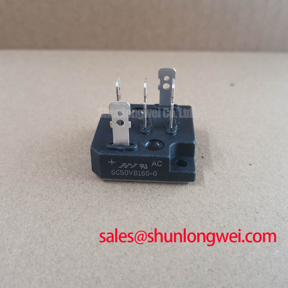
Inspect mounting-surface condition, terminal seating, and separation from adjacent conductors during reassembly. Apply package-specific fastening instructions rather than a generic bolt torque. Creepage and clearance assessment belongs to the equipment’s insulation design. For repeatable maintenance records, the Field Engineer’s Handbook provides a supporting framework for documenting measurement conditions, thermal observations, and post-repair checks.