Content last revised on September 25, 2026
Assembly Integrity & Layout Architecture: Implementing Reverse Recovery Charge for SC50VB160-G
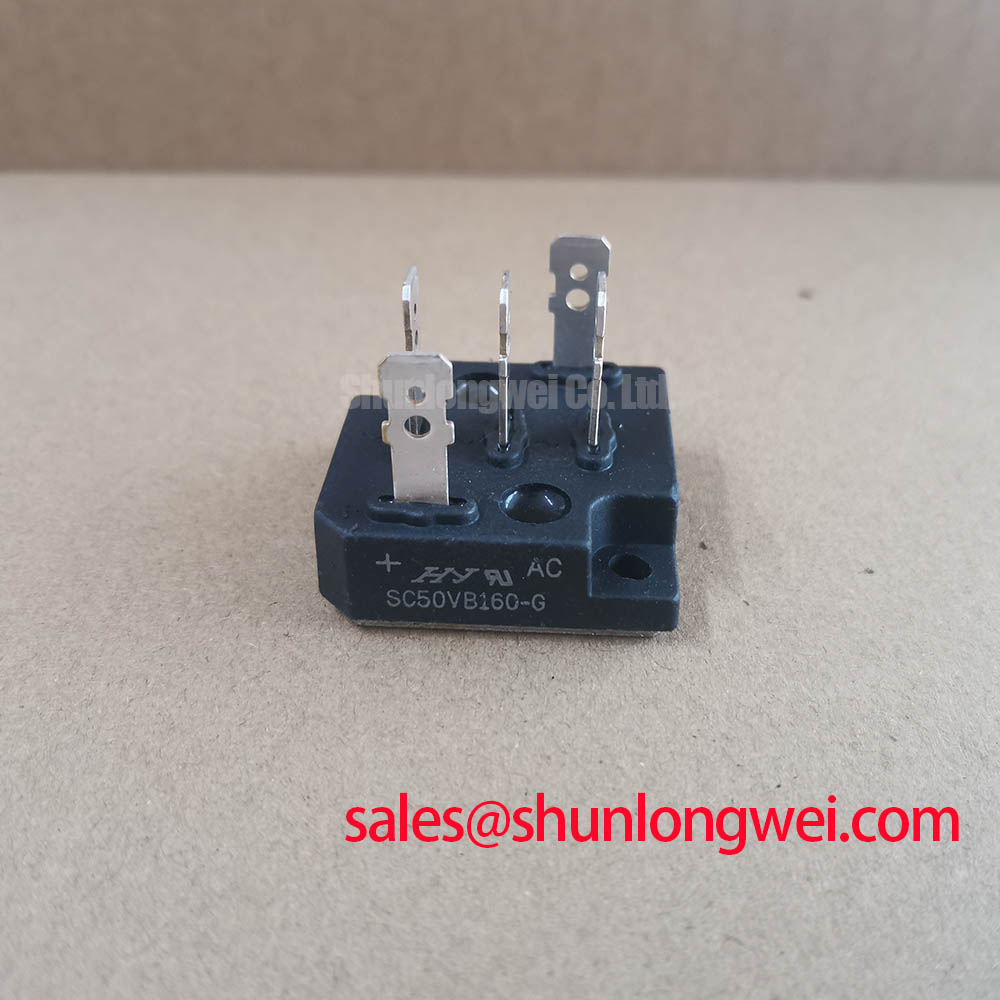
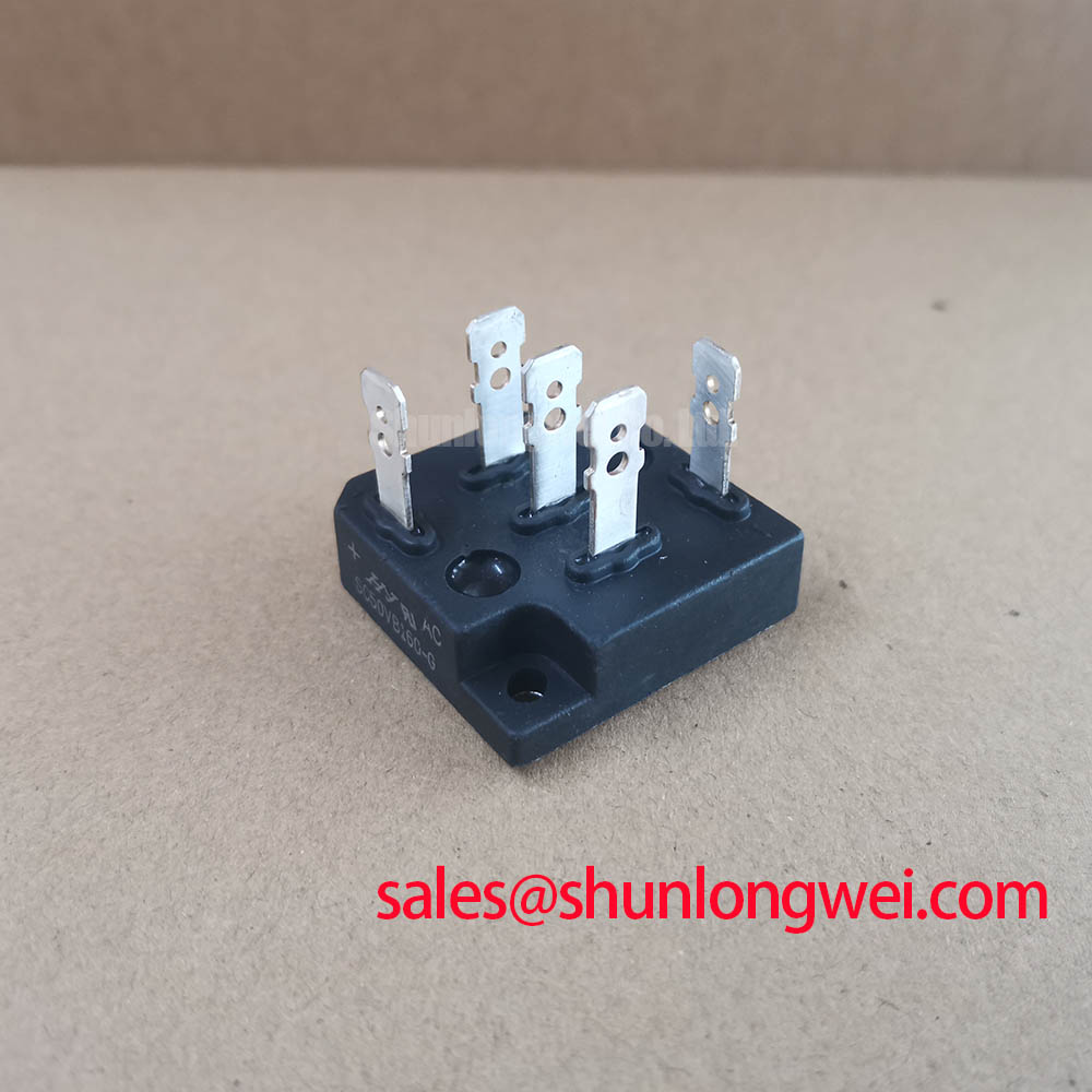
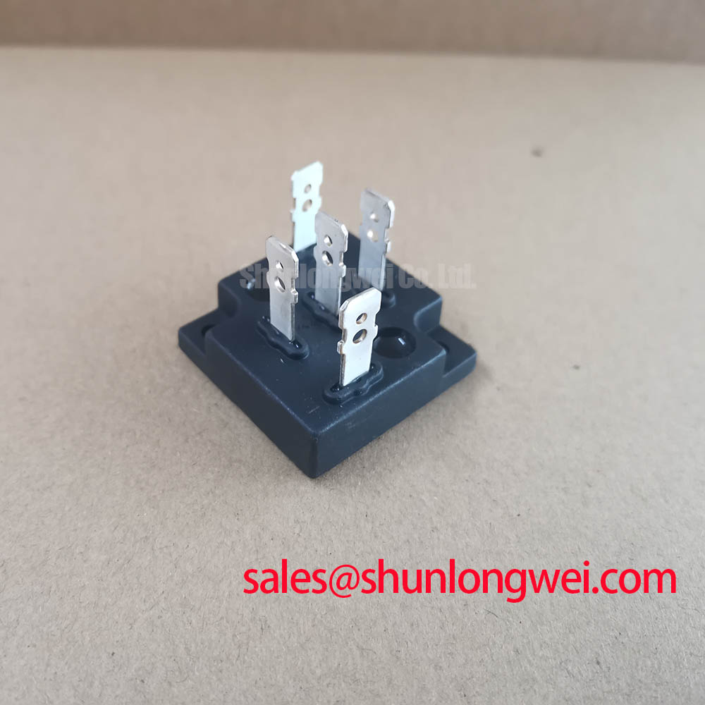
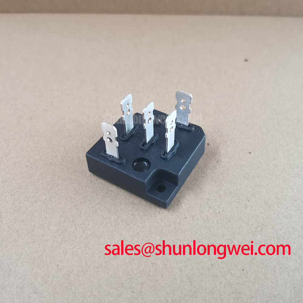
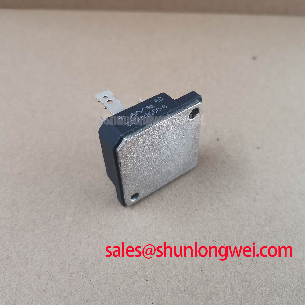
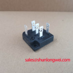
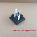
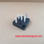
Begin the installation review by mapping every power terminal to the original schematic and checking that the replacement orientation matches the existing bridge connection. The official data supplied for this product confirms a 1600.0 V voltage rating, a 50.0 A current rating, and a Power Bridge Module package. It does not provide a terminal drawing in the available parameter set, so the system integrator should verify terminal identification from the original SC50VB160-G documentation rather than infer polarity or phase assignment from the enclosure position.
In an SVC or thyristor-switched capacitor cabinet, the bridge module can operate alongside contactors, reactors, capacitors, fuses, and controlled switching devices. The physical layout should preserve the original current path wherever practical. Short, symmetrical conductors help reduce unintended loop inductance, while separated control and power wiring can reduce the possibility of noise coupling into sensing circuits. These are Design Considerations, not factory guarantees for this specific module.
Reverse-recovery behavior is a system interface issue. A bridge device with a recovery current profile that differs from the original assembly can alter commutation stress, switching loss, and conducted noise even when its voltage and current ratings appear suitable. The supplied official parameter set does not state Irrm, trr, softness factor, or stored recovery charge for SC50VB160-G. Engineers should therefore compare those values in the applicable datasheet and confirm the result with a controlled waveform test before approving a replacement.
Measure the voltage across the module during the same operating sequence used by the original equipment. A differential probe with suitable common-mode capability should be connected according to the instrument manufacturer’s safety procedure. Observe the bridge voltage, current commutation, and any ringing at the switching transition. If the waveform differs from the known-good assembly, review conductor geometry, snubber condition, fuse type, reactor condition, and control timing before assigning the change to the module alone.
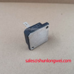
Thermal installation also requires evidence from the mechanical drawing. The available factory data does not state the mounting-hole pattern, base dimensions, insulation sheet requirement, heatsink flatness, thermal interface material, or fastening torque. These values must be taken from the relevant SanRex documentation or the original equipment service record. 💡 Pro Tip: Disconnect the cabinet from every energy source and verify the capacitor bank has reached a safe measured state before touching the bridge terminals or changing the module.
Thermal cycling deserves attention in bidirectional DC bus charging and discharging equipment. Repeated load changes can create expansion and contraction at the module, heatsink, busbar, and terminal interfaces. A service inspection should look for discoloration, loosened connections, cracked insulation, uneven contact pressure, and contamination around the cooling surface. The external thermal condition can be documented without claiming a field lifetime or failure rate that has not been published for this model.
For a broader topology review, the front-end relationship between the bridge and auxiliary rectification stage may be evaluated alongside DDB6U180N16RRP_B37. This is a neutral engineering reference, not a claim that the two devices are interchangeable or that they share the same electrical functions.
SC50VB160-G Operational Boundaries: Evaluating Type-2 Coordination: Sub-Cycle Dead-Short Limits
Short-circuit protection should be assessed from the complete protection chain rather than from the bridge module rating alone. The official 1600.0 V rating identifies the stated voltage class, while the official 50.0 A rating identifies the stated current class supplied for this product. Neither value, by itself, establishes the permitted duration of a dead short, the repetitive surge capability, or a suitable semiconductor fuse.
Type-2 coordination work normally compares the prospective fault current, fuse clearing behavior, wiring impedance, bus capacitance, and the semiconductor’s published withstand data. The supplied product information does not include an I2t value for SC50VB160-G, nor does it include a fuse coordination table. It would therefore be unsafe to publish a numerical fuse recommendation or claim that a particular protective device will prevent package damage.
The correct maintenance procedure is to collect the original fuse manufacturer, fuse class, rated voltage, pre-arcing data, total clearing data, and application record. Then obtain the bridge manufacturer’s surge-current and I2t limits for the exact product revision. Compare the protection curve with the equipment’s measured or calculated prospective fault current. This is an Engineering Recommendation; final acceptance belongs to the system designer responsible for the cabinet protection study.
For a capacitor-switching installation, the initial energization event may also include capacitor inrush, reactor interaction, and transient recovery voltage. These events should be captured during commissioning with current and voltage probes positioned at the bridge input and output. A fuse that survives normal operation may still be unsuitable if it clears too slowly during a high-energy fault, while an unnecessarily fast device may interrupt expected charging pulses. The selection must be supported by the fuse maker’s published data and the equipment coordination study.
Regenerative braking and high-power braking resistor systems present a related but different duty pattern. Their energy absorption path may place fast current changes near the DC link, but the SC50VB160-G should not be assumed to provide a braking-chopper function unless the original circuit documentation confirms that topology. Designers should identify whether the module is used for rectification, freewheeling, auxiliary conversion, or another bridge role before applying any protection conclusion.
When a fault has already occurred, record the fuse condition, terminal discoloration, heatsink contact marks, cable routing, and control sequence before removing the device. Compare all phases or bridge paths against a known-good assembly using an instrument and test voltage appropriate to the service procedure. A single resistance reading cannot prove dynamic semiconductor health, particularly when parallel paths, capacitors, or connected loads remain in the circuit.
Extreme operating environments should be treated as additional design variables. The supplied data does not state altitude derating, insulation coordination, environmental qualification, cosmic-ray performance, FIT data, or a guaranteed service life. These subjects require applicable manufacturer documentation or a recognized qualification source. A general power-electronics discussion can be found through Future of Power Electronics, but it should not be read as a product-specific approval for SC50VB160-G.
Assembly Integrity & Layout Architecture: Implementing Turn-On Current Rise Limiting: Preventing Stress for SC50VB160-G
Before adding or changing a snubber, identify the exact semiconductor topology used in the cabinet. A bridge rectifier module and a controlled thyristor assembly do not necessarily use the same trigger, commutation, or suppression network. The product information supplied here classifies SC50VB160-G as a Power Bridge Module, but it does not publish an internal circuit diagram, device count, individual die type, or recommended Rs and Cs values.
Snubber selection should begin with measured voltage overshoot and ringing at the device terminals under the actual bus voltage, load current, switching sequence, and wiring arrangement. The engineer should then determine whether the observed transient is associated with stray inductance, reverse recovery, capacitor ESR, reactor behavior, control timing, or a deteriorated suppression component. This avoids assigning every abnormal waveform to the bridge itself.
Where the original equipment uses an RC network, document the installed component values, voltage class, pulse capability, mounting position, and measured condition before replacement. The replacement capacitor must be suitable for the electrical stress and repetitive pulse duty established by the system designer. The resistor must be checked for pulse energy and thermal behavior under the real switching pattern. These are system-level requirements and are not official SC50VB160-G specifications.
A series reactor or current-limiting element can influence turn-on current rise, but its suitability depends on the complete power path. In capacitor-switched SVC equipment, reactor saturation, capacitor voltage, switching timing, and grid impedance can change the current waveform from one operating point to another. The correct engineering method is to verify the current rise and device terminal voltage over the intended operating envelope, then confirm that the measured stress remains within the published limits for the exact bridge device and connected components.
Thermal performance should be checked during the same test because switching loss and conduction loss are not independent of the waveform. Use the manufacturer’s thermal data when available and measure heatsink temperature, ambient conditions, airflow, and terminal temperature during representative duty. The provided parameter set does not contain thermal resistance, junction-temperature limits, or transient thermal impedance, so no numerical thermal margin can be assigned here.
For qualification, include the load transitions that matter to the equipment: DC bus charge and discharge, capacitor-bank switching, reactive-power steps, and regenerative energy transfer where applicable. Record current sharing between parallel paths if the cabinet uses them. Any mismatch should lead to a review of conductor length, busbar symmetry, contact resistance, and gate or control wiring rather than an immediate assumption of manufacturing variation.
Thermal shock is a packaging and materials concern that should be evaluated with an appropriate test plan rather than inferred from the nominal voltage and current ratings. Background information on Thermal Shock Testing for Power Modules can help frame the subject, while product-specific acceptance criteria must come from the manufacturer or the equipment qualification plan.
Benchtop Waveform Tuning: Mitigating Stress via Gate Trigger Current Temperature Dependence on SC50VB160-G
Do not connect a gate-trigger test circuit to SC50VB160-G until the exact internal device topology and terminal definition have been confirmed. The supplied official description identifies a bridge module, but it does not state a gate terminal, gate trigger current, gate holding current, gate pulse rise-time requirement, or multi-pulse firing recommendation. Those values must not be inferred from the product name or from a nearby thyristor module.
If the installed system includes an adjacent controlled semiconductor stage, tune that stage separately from the bridge rectifier. First trace the command source, isolation device, return path, and power reference. Then verify the trigger waveform at the receiving terminals with an instrument suitable for the circuit’s common-mode voltage. A pulse that appears correct at the driver output may be distorted by cable inductance, reference movement, isolation capacitance, or a shared return path before it reaches the controlled device.
Temperature-dependent behavior should be reviewed using the original manufacturer’s electrical limits and a controlled environmental procedure. The available SC50VB160-G data does not provide a temperature range, gate sensitivity curve, holding-current curve, or switching qualification. It is therefore not appropriate to publish a fixed trigger current, negative cutoff bias, or timing prescription for this product.
Gate-driver layout remains relevant when a neighboring thyristor or transistor stage shares the same cabinet. Minimize the power-current loop and the control-return loop, keep high-current commutation conductors away from sensitive command wiring, and verify the result with differential measurements. These are Design Considerations. The system engineer should determine whether a negative cutoff bias, shield arrangement, ferrite component, or revised return path is required after measuring common-mode ground movement.
During bench testing, begin with a current-limited and isolated setup appropriate to the equipment voltage class. Confirm the command sequence at low stored energy before progressing to full operating conditions. Observe the relationship between control timing, bridge terminal voltage, load current, and heatsink temperature. If the module is part of a bidirectional DC conversion path, test both energy-flow directions because charging and discharging can produce different commutation conditions.
A waveform anomaly should be investigated through the complete signal path. Check probe placement, reference integrity, driver supply stability, isolation status, cable routing, and the condition of suppression components. If a control pulse is missing or distorted, the observation may indicate a driver, wiring, reference, or topology issue rather than a failed bridge. Compare against the known-good channel and confirm with repeated measurements before authorizing component replacement.
For procurement and maintenance records, retain the manufacturer name SanRex (Sansha Electric), model SC50VB160-G, official rated voltage 1600.0 V, official rated current 50.0 A, and package description Power Bridge Module. Cross-model evaluation may include PGH50N16, but electrical equivalence, mechanical fit, protection coordination, and operating behavior must be verified independently before any substitution is considered.