

Content last revised on October 5, 2026
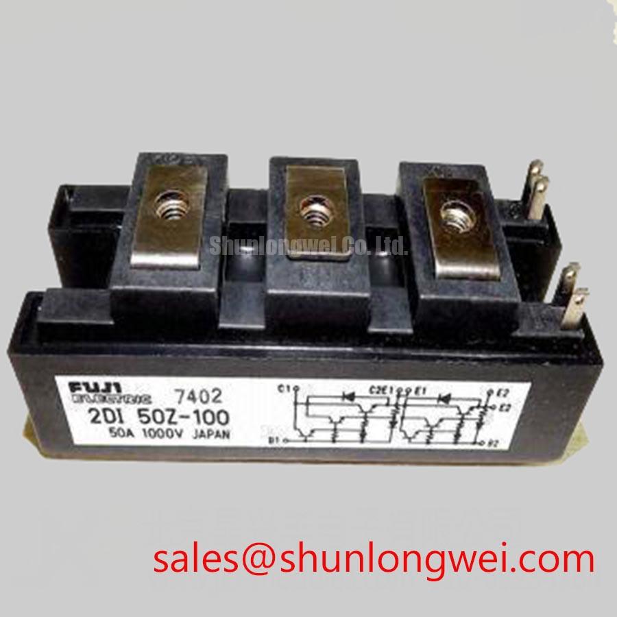
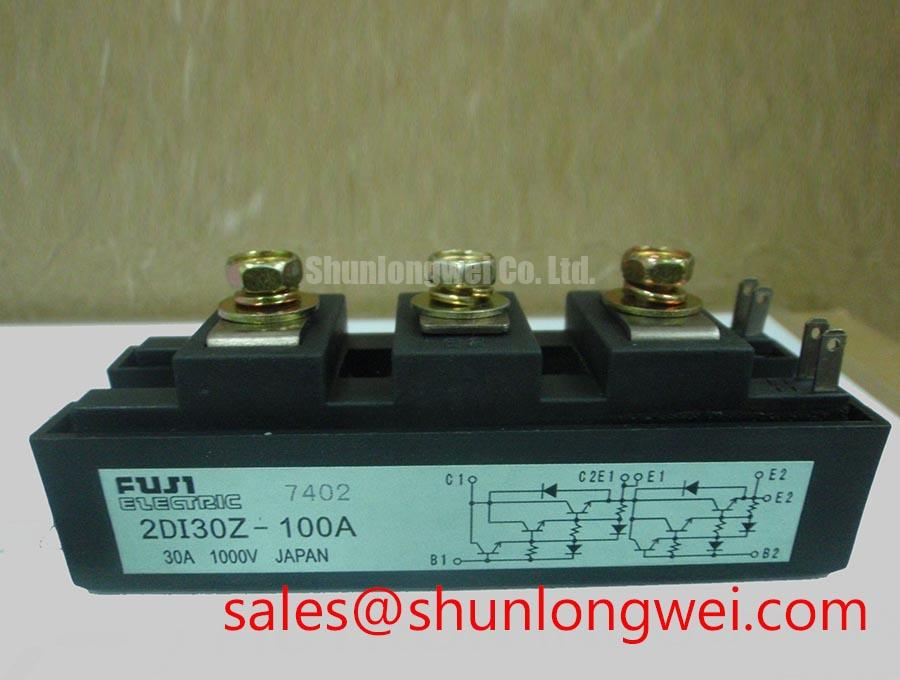
With the rectifier isolated and its stored energy discharged, compare the installed module’s markings, terminal arrangement, and mounting footprint with the replacement documentation before disturbing the connections. The 2DI30Z-100 is a Fuji Electric power diode module with a 1000 V rated voltage and 30 A rated current, stated here as Official Specifications. Those ratings identify the part for an initial review; they do not establish its surge withstand, fuse coordination, thermal performance, or mechanical interchangeability.
2DI30Z-100 Operational Boundaries: Evaluating Turn-On Current Rise Limiting
A diode module does not have a gate command that can be adjusted to control turn-on. Current begins to flow when the applied circuit conditions forward-bias a conducting path. In a rectifier repair, the first useful check is therefore the original circuit drawing: identify the module’s connected nodes, AC or DC circuit role, upstream impedance, DC-link capacitance, and any existing protection around the rectifier. Match each connection to the module’s documented terminal diagram rather than inferring polarity from cable position.
The 1000 V voltage rating and 30 A current rating are Official Specifications for 2DI30Z-100. A maintenance engineer should also obtain the applicable Fuji Electric datasheet and check the conditions attached to those ratings, including temperature and cooling assumptions. Neither number, by itself, defines permissible charging inrush or repetitive transient current. Where a large downstream capacitor is present, record its charging path and inspect the intended precharge or input-limiting arrangement before energizing the assembly.
Design Consideration: RC networks can be evaluated where measured voltage transients or commutation behavior call for damping, but their resistor and capacitor values must come from the actual source impedance, waveform, and component ratings. A series reactor, including a saturable reactor if the existing equipment specifies one, likewise requires circuit-level verification of current rise, losses, and normal operation. Neither accessory should be assumed necessary solely because this module is used in a rectifier.
For a replacement assessment, compare topology and terminals as carefully as headline ratings. The separately listed 6RI30G-160 can be reviewed as another rectifier-module candidate during materials planning, but its circuit configuration, electrical limits, dimensions, and mounting details must be checked against the equipment documentation before any interchange decision. Fuji Electric’s power semiconductor information provides manufacturer context; the part-specific documentation remains the authority for limits not stated on this page.
Field Diagnostics and Commissioning: Fuse Coordination for 2DI30Z-100 Rectifier Circuits
When a module has failed after a short circuit, retain the upstream fuse identification and examine the fault path before replacing either item. Check for damage at the DC load, cabling, bus connections, and input protection, then compare cold-state diode-test readings with the documented module circuit. An unexpected reading can reflect a parallel path through the installed equipment, so isolate connections as the service procedure permits before treating it as a module finding.
Fuse coordination cannot be established from the 1000 V and 30 A Official Specifications alone. The comparison needs the fuse manufacturer’s clearing characteristics at the available fault current and the diode module’s documented non-repetitive surge-current and I²t limits under their stated conditions. No part-specific I²t withstand value or coordination table is provided here. Without those documents, a claim that a fuse will prevent module damage during a dead short would be unsupported.
Engineering Recommendation: Ask the system engineer to compare the complete clearing duty of the selected fuse with the module’s applicable short-duration limit, accounting for the available fault current and the installation’s operating temperature. The fuse’s position matters: a device upstream of several branches may not isolate the same fault as one dedicated to the rectifier. Record the actual fuse designation, its location on the schematic, and the measured or calculated prospective fault conditions before approving a changed protection arrangement.
At commissioning, verify terminal identity and connection tightness against the equipment and module instructions. Measure input and output behavior under a controlled startup, then inspect for unusual heating at accessible connections using the site’s approved method. A warm terminal alone does not identify a defective diode; contact resistance, conductor preparation, and load conditions also merit inspection. For background on switching-device mechanisms encountered elsewhere in a power cabinet, The Ultimate IGBT Knowledge Base is relevant, while diode-module protection decisions must still be based on the rectifier circuit and its own ratings.
Assembly Integrity and Input Protection: Spark Gaps, MOVs, and 2DI30Z-100
Trace the protection layout from the AC supply to the rectifier before moving a conductor. Note the positions of any spark gap, metal oxide varistor, fuse, and RC stage, including their return paths. A protective part located far from the conductors it is intended to protect can leave substantial wiring in the transient path. Keep the protection review tied to the equipment drawing and physical cabinet layout rather than assuming that the presence of an MOV establishes protection at the diode terminals.
Design Consideration: Input surge protection is a system-level coordination task. The engineer selecting an MOV or spark gap should evaluate the supply’s normal voltage, expected transient exposure, upstream protection, and the voltage appearing at the rectifier during the relevant event. An RC stage should be assessed separately for its damping purpose and continuous electrical stress. No MOV clamp level, spark-gap setting, or snubber value is identified as an Official Specification for 2DI30Z-100.
IEC 61000-4-5 describes surge immunity testing at the equipment level; it is not a standalone compliance rating for this diode module. If the rectifier belongs to equipment with a surge-test requirement, the protection network and enclosure wiring need to be assessed in that complete configuration. Fuji Electric’s power semiconductor and module information can help locate manufacturer product resources, but the original equipment protection specification and the exact module documentation govern this repair.
A high-current green hydrogen electrolyzer DC power rectifier is one possible equipment context for assessing a diode module, not an established installation for this part. Before considering 2DI30Z-100 for that circuit, confirm whether the module’s documented current conditions, input topology, cooling arrangement, and fault protection match the particular rectifier stage. The equipment’s overall output current must not be mistaken for the rating or duty of an individual module position.
Assembly Integrity and Heatsink Contact Pressure for 2DI30Z-100
Before mounting the replacement, inspect the heatsink land for debris, raised burrs, damaged threads, and residue from the previous thermal interface. Check that the module sits evenly without using the fasteners to pull a visibly distorted assembly flat. Apply the specified interface material according to the module and equipment instructions; an apparently generous coating is not evidence of good thermal contact.
No part-specific mounting torque, fastening sequence, or junction-to-case thermal resistance is supplied in the Official Specifications stated here. Obtain those values from the applicable manufacturer documentation before setting a torque tool or assessing a thermal model. Heatsink temperature on its own cannot establish junction temperature: the interpretation also depends on losses, thermal resistance, contact quality, and airflow under the actual operating conditions. Record the mounting procedure used so a later inspection can distinguish a documented assembly from an uncertain one.
Maintenance Note: Periodically clear the heatsink airflow path and investigate rising connection or heatsink temperatures against the equipment’s established operating baseline. During that inspection, look for drying or displacement of interface material where the maintenance procedure calls for disassembly, and check fastener condition using the approved service instructions. In cabinets exposed to changing temperatures, inspect for moisture or condensation before restart; enclosure climate control and the permitted energizing procedure are system decisions, not properties established by the diode module’s voltage and current ratings.
After reassembly, confirm that power terminals are routed without mechanical strain and that insulating barriers and covers are restored. Observe the rectifier through its controlled startup and subsequent loaded operation, recording current, accessible temperatures, and any change from the known-good baseline. If heating is uneven, reassess electrical loading, terminal contact, airflow, and heatsink seating before attributing the observation to a single cause.