Content last revised on October 6, 2026
Benchtop Waveform Tuning: Diode Recovery Stress on MP508W
| Manufacturer | Micro Commercial Components (MCC) |
|---|---|
| Part Number | MP508W |
| Product Category | Bridge Rectifier Module |
| Rated Current | 50.0 A |
| Package | Metal Case Bridge |
| Voltage Classification | Standard Industrial Rating |
Probe the rectifier output and each AC terminal during controlled energization, then compare commutation spikes, conduction balance, and recovery behavior against a known-good assembly. The MP508W is specified as a 50.0 A bridge rectifier module in a metal case bridge package; the available factory parameter set does not state numerical values for peak reverse recovery current, reverse recovery time, or soft-recovery classification.
For a high-voltage three-phase motor solid-state soft starter, waveform verification should therefore focus on the actual commutation event rather than assuming a particular diode recovery profile. Use a suitably rated differential probe and observe the voltage across the rectifier during firing-angle changes. Excessive ringing can be associated with commutation-loop inductance, wiring geometry, snubber behavior, or semiconductor recovery characteristics, so the corrective action should follow measured evidence.
Record the terminal arrangement from the applicable manufacturer connection drawing before removing the original device. The supplied product information does not provide a fuse coordination table, terminal torque value, or I2t limit for this model. Those values should not be substituted with generic bridge-rectifier assumptions when coordinating semiconductor fuses or evaluating a failed soft-starter phase.
MP508W Circuit Protection and Phase-Controlled Rectification
Measure the three phase currents and DC output while stepping the firing angle through the intended control range, including the requested 0° to 150° evaluation window. Check current sharing, output smoothness, line displacement, and controller synchronization at each operating point instead of judging compatibility from the 50.0 A rating alone.
Phase-controlled rectification changes the relationship between motor acceleration, average DC output, reactive demand, and harmonic current. The MP508W product data supplied here confirms a standard industrial voltage classification but does not state a numerical repetitive peak reverse voltage, surge current, or fuse I2t value. System engineers should verify those missing boundaries from the original device documentation before selecting a replacement for a high-voltage soft-starter power stage.
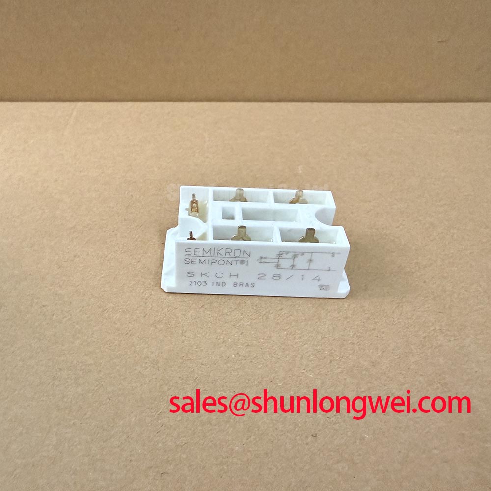
During protection testing, inspect the semiconductor fuse path, gate or firing control timing, and phase-to-phase current symmetry together. A shorted bridge leg, incorrect terminal mapping, or a firing circuit fault may produce similar current imbalance. A neutral replacement decision should be based on isolation testing, controlled current measurement, and waveform comparison. The SKD 25/14 may be reviewed as a separate device in a replacement assessment, but electrical and mechanical interchangeability must be established by the system designer.
Assembly Integrity and Heatsink Contact for MP508W
Inspect the metal base, mounting surface, fasteners, and thermal interface immediately after removing the module, then check for uneven contact marks or distortion before installing the replacement. The MP508W package is identified as a Metal Case Bridge, while the supplied factory data does not specify junction-to-case thermal resistance, allowable case temperature, mounting torque, or base dimensions.
As a Design Consideration, the heatsink should provide a flat, clean contact surface and stable mechanical pressure across the module base. Apply only the thermal interface method approved for the equipment assembly, avoiding contamination of terminals or excessive compound that could compromise mechanical seating. Thermal validation should use measured case temperature, ambient conditions, load current, and the actual enclosure airflow rather than a generic temperature estimate.
Keep high-current paths short and symmetrical where practical, and separate measurement wiring from high di/dt commutation loops. This reduces the chance that probe wiring or unequal bus resistance will conceal phase imbalance. 💡 Pro Tip: Use the original manufacturer mounting torque specification whenever available, because an assumed fastener value can change both thermal contact and package stress.
Assembly Integrity and Surge Evaluation During High Peak Current
Capture the current and voltage during the first controlled half-cycle of a high-current test, then compare the result with the protective fuse clearing behavior and the thermal state of the assembly. The supplied MP508W parameters do not include a numerical sinusoidal 10 ms half-cycle surge rating, ITSM, non-repetitive peak current, or junction-temperature limit, so these boundaries must not be inferred from the 50.0 A continuous rating.
For a soft starter exposed to motor inrush or an abnormal commutation event, verify the semiconductor fuse coordination, fault-clearing time, bus inductance, and reapplication of reverse voltage as one protection network. A fuse selected only by nominal current can fail to coordinate with a bridge during a short, while an unsuitable layout can increase the voltage stress seen during current interruption. The final protection envelope requires controlled testing against the equipment DC-link and line conditions.
Reliability work should also consider the enclosure environment and service procedure. The IEC 61000-4-2 Electrostatic Discharge immunity standard provides a reference for system-level ESD testing, but it does not represent an independent certification of this rectifier module. For broader power-conversion architecture context, engineers can consult The Race for Efficiency. Enclosure water and dust protection should be assessed separately against the applicable IP code definitions.