

Content last revised on October 28, 2026
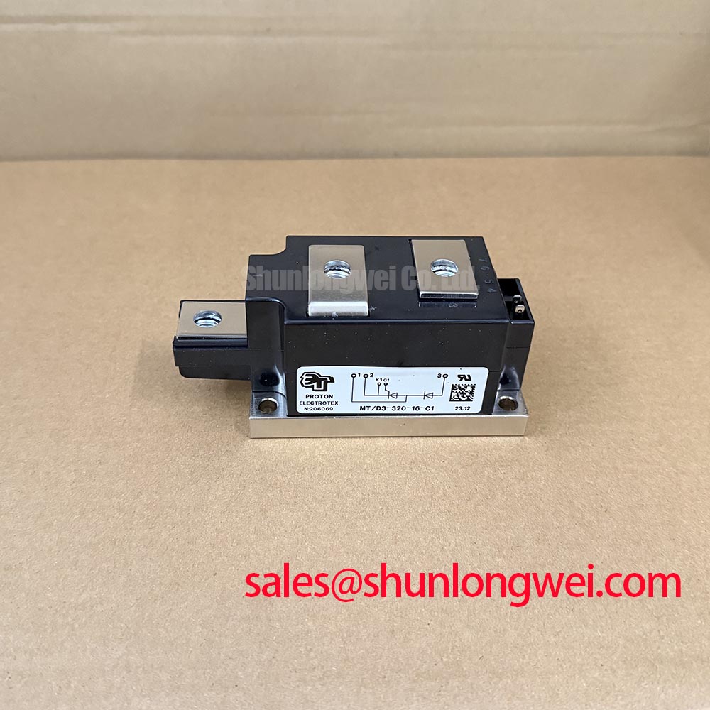
MT/D3-320-16-C1 Thermal Electrical Optimization for High di/dt Gate Firing
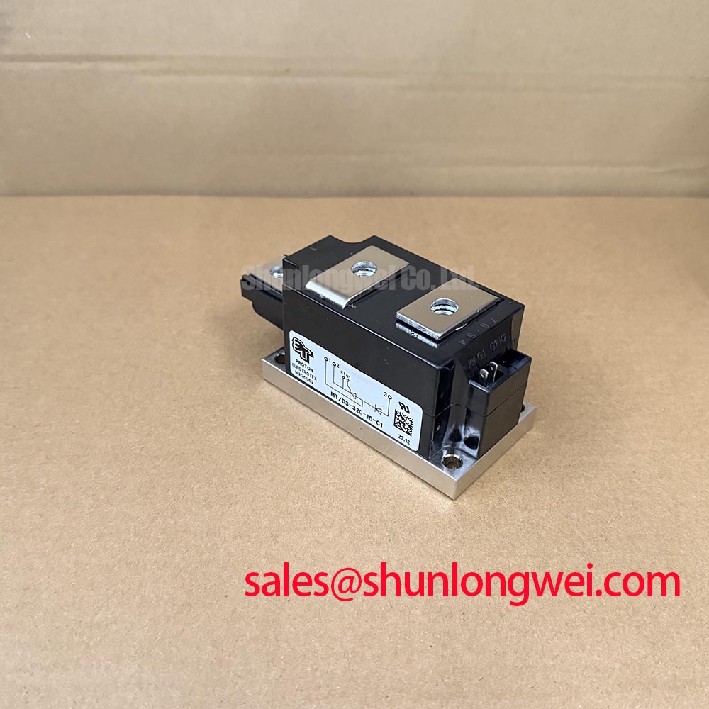
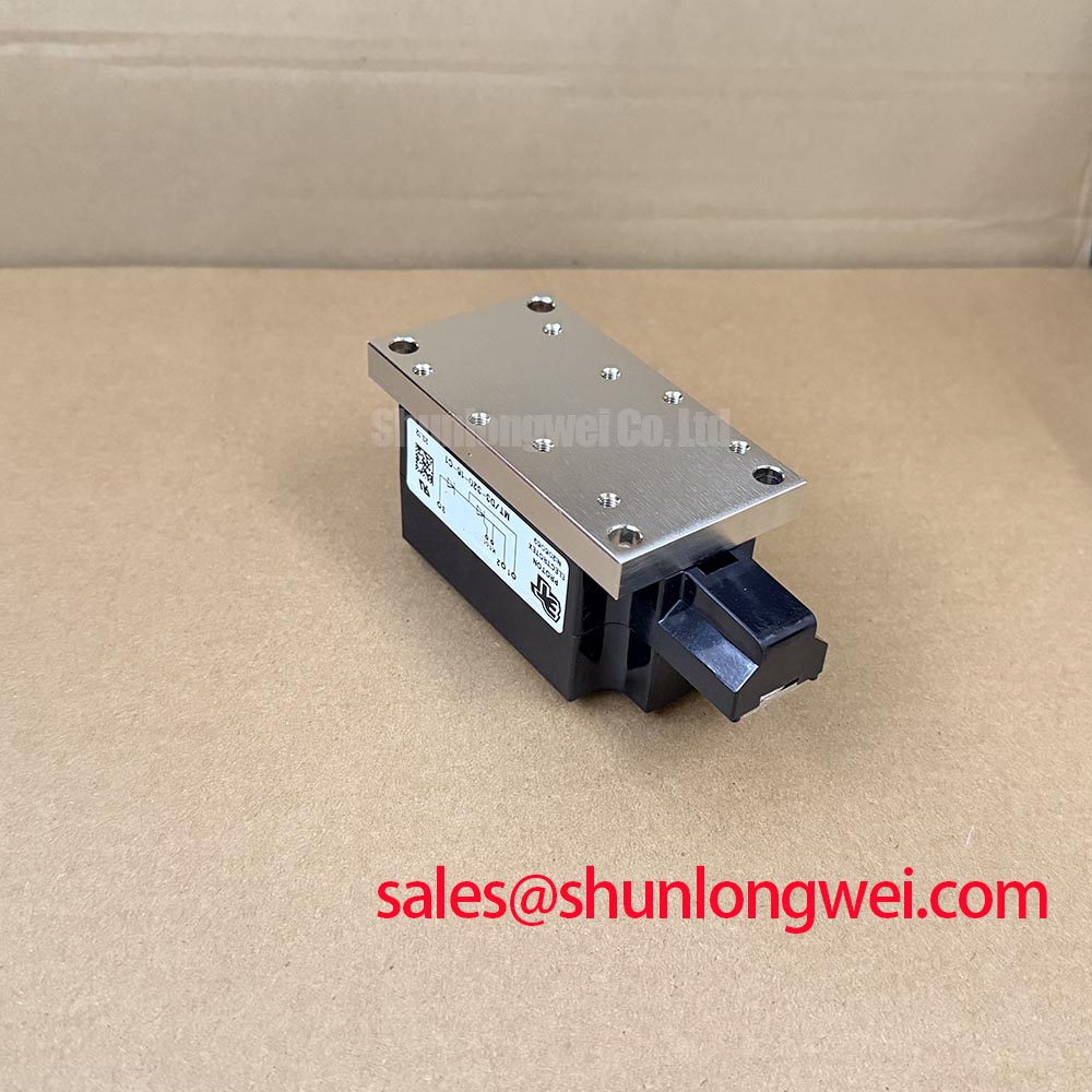
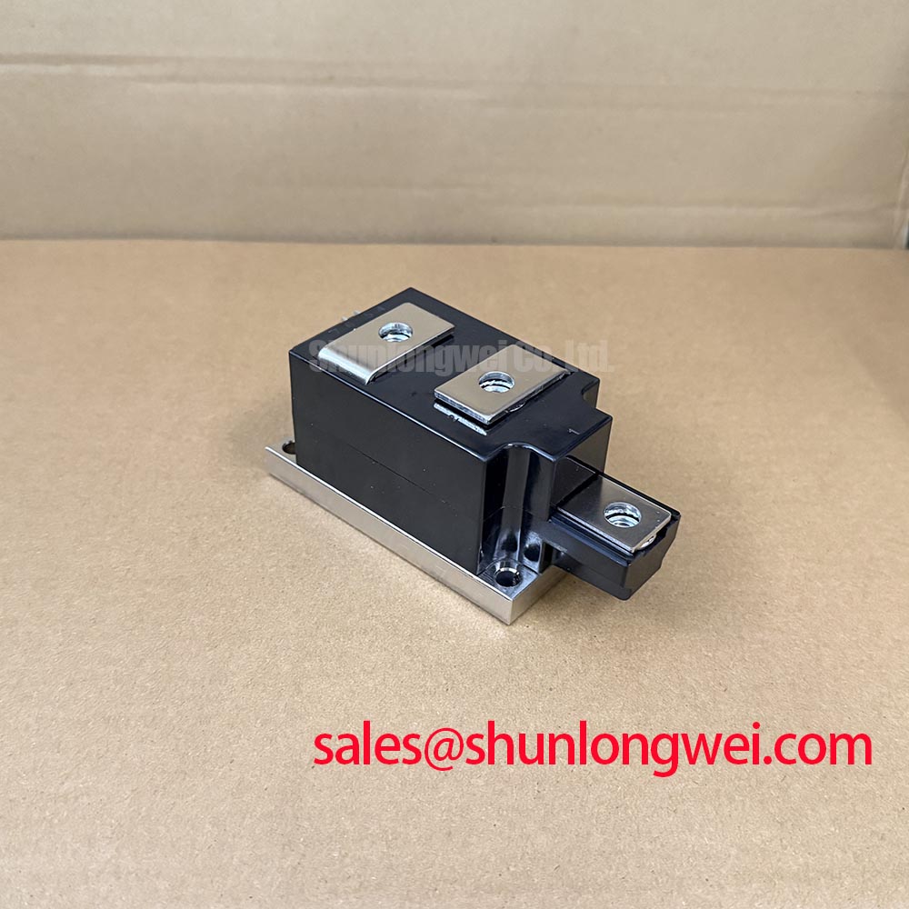
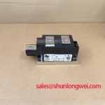
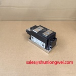
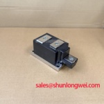
With the furnace isolated and stored energy safely discharged, check the main terminals for unintended low resistance, inspect the power module body for cracking or heat discoloration, and confirm that the replacement footprint matches the original assembly before reconnecting the firing circuit. The MT/D3-320-16-C1 is a SanRex (Sansha Electric) thyristor / diode power module intended for evaluation in industrial power conversion equipment.
Confirm the voltage and current ratings, their specified conditions, and the package details from the applicable manufacturer datasheet. The system engineer should match the original circuit documentation, terminal arrangement, cooling method, and protection components before energizing the assembly.
Gate firing should be examined as a complete pulse path rather than as an isolated trigger signal. In a medium frequency induction melting or metal hardening power supply, the firing transformer or isolation stage, gate resistor network, return conductor, and thyristor terminal connections all influence the delivered pulse. A rapid gate current rise, including a design target above 1 A/µs where required by the control architecture, should be validated against the module’s gate limits and with the actual driver and wiring rather than assumed from the module designation.
When a controller uses a pulse train, the initial pulse should establish reliable triggering while the back porch maintains sufficient gate drive until the thyristor reliably latches. Excessive pulse repetition, poor return routing, or unequal wiring between parallel devices can concentrate gate heating in one device. Designers should tune pulse timing against the actual load current, commutation behavior, and gate waveform measured at the module terminals.
For installations involving multiple parallel power paths, positive temperature coefficient behavior can assist static current sharing only where confirmed by the device characteristics at the relevant operating point. It does not remove the need to compare conductor resistance, busbar geometry, thermal interface condition, and switching timing. Dynamic sharing must be checked during current transitions because unequal stray inductance can produce different gate and anode current profiles.
Terminal surfaces should be clean, flat, and mechanically secure. Use the manufacturer’s specified tightening data; if it is unavailable, obtain approved assembly instructions rather than inferring torque from the fastener size alone. Field Alert: never insert or remove gate and power connectors while the DC link or control supply remains energized.
MT/D3-320-16-C1 Circuit Protection and Type 2 Coordination
Semiconductor fuse coordination must be assessed from the selected fuse clearing I²t, prospective short circuit current, circuit impedance, and the thyristor or diode withstand data for the complete assembly. A fuse label alone does not establish Type 2 coordination. The protection review should compare the fuse manufacturer’s total clearing I²t and peak let-through current with the module’s applicable nonrepetitive surge withstand limits under compatible conditions, then confirm that the fuse operates within the permitted fault duration. Repetitive current limits must be checked separately for recurring overloads.
| Evaluation item | MT/D3-320-16-C1 | PDMB 200E6 |
|---|---|---|
| Manufacturer | SanRex (Sansha Electric) | Product documentation required |
| Product category | Thyristor / Diode Module | Power semiconductor module |
| Voltage ratings | Consult the applicable datasheet | Consult the applicable datasheet |
| Rated current and conditions | Consult the applicable datasheet | Consult the applicable datasheet |
| Replacement decision | Verify terminals, ratings, cooling, and gate interface | Compare against the original circuit |
The linked PDMB 200E6 can be included in a neutral replacement assessment, but physical fit and electrical equivalence must be established from the relevant documentation. In a rectifier and controlled power topology, the complementary stage may also be reviewed alongside PD431807. The correct choice depends on the original bridge arrangement, firing sequence, current path, and protection coordination.
For a dead short, inspect the fuse, busbar, snubber, gate driver output, and module terminal condition as one fault chain. A failed fuse with an undamaged module does not prove that the protection system is correctly coordinated, while a damaged module does not identify the initiating fault without checking the gate circuit and transient records.
Transient Dynamics and AC Input Protection Coordination
Where used, primary spark gaps, MOVs, and RC snubbers should be coordinated as separate protection layers for the thyristor junctions. The MOV selection must suit the actual AC line, repetitive peak voltage, temporary overvoltage exposure, and surge current environment. The spark gap must not be treated as a substitute for correctly placed clamping and current limiting.
RC snubber placement is a layout decision. The loop should be kept compact to reduce parasitic inductance, while the component voltage and pulse energy ratings must be matched to the switching waveform. During commissioning, compare the voltage at the module terminals with the control timing and look for ringing, asymmetric overshoot, or repeated triggering. Long motor or transformer cables can behave as transmission paths and may reflect switching edges back toward the power stage, so cable routing and filtering should be assessed at the equipment level.
Gate loop damping also deserves attention where the driver is separated from the module by a cable or isolation board. Minimize the gate loop area, separate power commutation paths from sensitive firing returns, and verify that the isolation device maintains adequate common mode transient immunity under the measured switching conditions. The practical design reference Precision Gate Drive Design provides additional guidance for this part of the control interface.
For industry cross-checking, engineers may consult the Mitsubishi Electric diode module lineup and the SanRex Sansha Electric power semiconductor module resource. These references support general topology and application evaluation; they do not replace the module-specific terminal, thermal, and protection data required for the installed system.