Content last revised on September 17, 2026
Assembly Integrity & Layout Architecture: Implementing Semiconductor Protection Fuse Selection for PD431807
The PD431807 from SanRex (Sansha Electric) is classified as a thyristor/diode module with a repetitive peak off-state voltage, VDRM / VRRM, of 1800 V and an average on-state current, IT(AV), of 700 A. These are Official Specifications. Its specified RMS on-state current is IT(RMS) = 1100 A, while the peak one-cycle surge current at 60 Hz is ITSM = 32,100 A. Those ratings identify electrical boundaries; they do not establish the permissible current of a complete soft-starter phase assembly without thermal, duty-cycle, conductor, and cooling analysis.
| Characteristic | Symbol | Official Specification | Integration relevance |
|---|---|---|---|
| Repetitive peak off-state voltage | VDRM / VRRM | 1800 V | Reference boundary for repetitive blocking stress |
| Average on-state current | IT(AV) | 700 A | Must be interpreted with the applicable thermal conditions |
| RMS on-state current | IT(RMS) | 1100 A | Relevant to conductor, terminal, and phase-current evaluation |
| Peak one-cycle surge current at 60 Hz | ITSM | 32,100 A | Nonrepetitive surge boundary, not a normal operating target |
| Fusing integral at 8.3 ms | I²t | 6.60 × 10⁶ A²s | Reference limit for semiconductor fuse coordination |
| Operating junction temperature | TJ | −40 to +125 °C | Junction boundary requiring system-level thermal verification |
| Isolation voltage at 25 °C | VISO | 3000 V RMS | Specified isolation test rating, not the continuous working voltage |
| Gate trigger current | IGT | 200 mA | Gate-driver compatibility checkpoint |
| Gate trigger voltage | VGT | 4.5 V | Gate-drive compliance checkpoint |
Fuse selection should begin with the manufacturer’s time-current and total-clearing I²t tables at the actual prospective fault current and AC system voltage. As an Engineering Recommendation, the fuse’s total-clearing energy should remain below the module’s specified 6.60 × 10⁶ A²s at 8.3 ms under the evaluated fault condition. Pre-arcing I²t alone is insufficient because current continues while the fuse arc is being extinguished. Fuse voltage rating, breaking capacity, ageing under repeated starts, enclosure pressure, and upstream protective-device coordination also remain system-determined.
The 32,100 A one-cycle surge rating should not be substituted for the fuse-clearing limit or interpreted as repetitive overload capability. A coordination study should use the lowest applicable semiconductor withstand boundary across operating temperature and should include the available short-circuit current of the transformer, cables, busbars, and supply. No fuse selection can promise the absence of enclosure damage under every dead-short condition; containment and fault-energy control require assessment at equipment level.
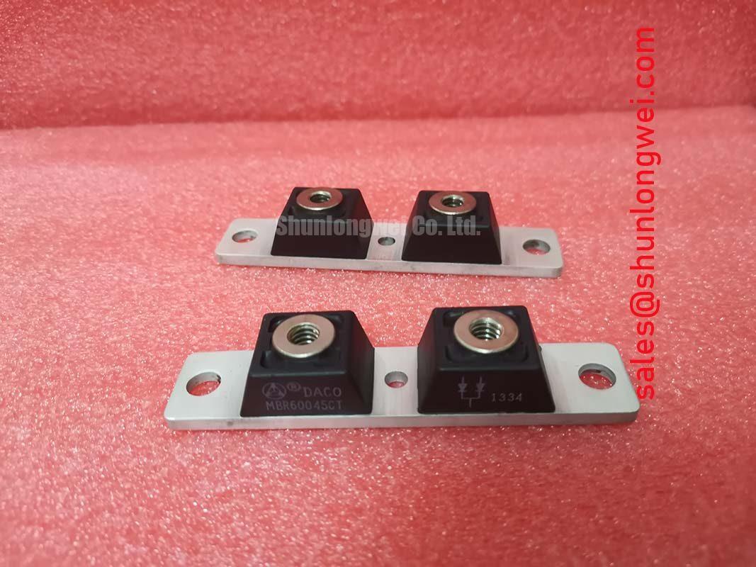
Before installation, identify every power and gate terminal from the original SanRex drawing rather than inferring the circuit from case appearance. Inspect terminal flatness, threads, insulating barriers, and creepage paths. The supplied parameter set does not state package dimensions, terminal designations, or fastening torque, so those details must come from the original mechanical documentation. Tightening torque should not be copied from another module merely because its fastener looks similar. Engineers comparing form, circuit arrangement, and ratings may also review the PD104VT2T1, but interchangeability requires independent confirmation of footprint, terminals, polarity, electrical limits, and thermal behavior.
Field Diagnostics & Commissioning: Thermal Interface Material Spreading Across PD431807 Topologies
Start thermal commissioning by cleaning the heatsink contact area, checking it for burrs and embedded debris, and confirming that the mounting plane does not rock beneath the module. Thermal interface material should fill microscopic surface voids without becoming a mechanical spacer. Its chemistry, application method, and finished thickness are Design Considerations determined by the heatsink finish, interface-material supplier, mounting hardware, and original SanRex assembly instructions.
The available official data specifies a junction operating range of −40 to +125 °C, but it does not provide Rth(j-c), Rth(c-s), case-temperature limits, baseplate construction, or a prescribed thermal-paste thickness. A junction-temperature estimate therefore should not be presented as a product-specific calculation until the complete thermal data and its measurement conditions are available. During commissioning, engineers can measure accessible case and heatsink temperatures at repeatable locations, record ambient and phase current, and compare all phases during an identical start sequence. An abnormal phase difference may justify checking contact pressure, current sharing, firing symmetry, bypass timing, airflow, and sensor placement rather than assigning a single cause.
Apply fasteners in the sequence stated by the original mechanical instructions so the module seats progressively. The tightening tool should be calibrated, and the specified torque must be taken from the matching package drawing. Excess paste can mask poor flatness and contaminate terminals, while insufficient coverage can leave local air gaps. After an initial controlled thermal run, inspect the interface spread pattern only if removal is permitted by the maintenance procedure; a uniform witness pattern is useful evidence, but it does not replace temperature measurement under load.
💡 Bench Tip: De-energize and discharge the power assembly before resistance or diode-mode comparison, and use ESD-safe handling on the gate terminals.
The module’s 3000 V RMS isolation rating at 25 °C is an Official Specification associated with defined test conditions. It should not be treated as permission to apply that voltage during routine incoming inspection. Production hipot voltage, ramp, duration, leakage threshold, and connected terminals must follow the manufacturer’s test method and the equipment safety plan. Surface contamination, insufficient terminal clearance, wiring displacement, and conductive mounting debris can compromise the assembled system even when the component has the stated isolation rating.
For incoming static checks, use an instrument with controlled test energy. Record gate-to-cathode resistance in both lead orientations and compare it with approved reference data or a known-good unit tested at similar temperature. A diode-mode difference may indicate a connection, meter, temperature, or device issue; it is not enough by itself to declare a failure. High-current conduction testing requires a protected fixture, controlled gate pulses, and suitable thermal monitoring rather than a handheld-meter result.
Assembly Integrity & Layout Architecture: Implementing Thermal Duty Cycle Management of Bypass Contactors for PD431807
In a high-voltage three-phase motor solid-state soft starter, the PD431807 can be evaluated as part of the controlled conduction path, subject to confirmation of the original circuit topology and terminal map. Phase-angle control progressively changes the applied motor voltage during acceleration, while a correctly coordinated bypass contactor can carry steady-state current after the motor reaches the intended operating condition. This operating role is an application assessment, not an official statement that the module is dedicated to one equipment platform.
A common Design Consideration is to reduce direct-on-line locked-rotor current, often discussed as approximately six to eight times motor rated current, toward a project target below 2.5 times rated current. That target is system-dependent and cannot be guaranteed by the module. Motor impedance, driven-load torque, acceleration time, supply stiffness, firing angle, current feedback, and allowable starts per hour determine whether it is achievable. Excessively aggressive current limiting can lengthen acceleration and increase semiconductor heating even when the measured line current appears lower.
The controller should verify phase sequence and establish symmetrical firing across all three phases. The official gate trigger values are IGT = 200 mA and VGT = 4.5 V. Gate-driver design must account for the stated trigger requirements, pulse duration, isolation, temperature, noise immunity, and the driver’s available compliance at the module terminals. The values should not be interpreted as a universal continuous gate-drive prescription. Lead routing should separate gate paths from high-current conductors and reduce coupled transients, with final performance confirmed by isolated waveform measurements.
Bypass transfer should occur only after the controller confirms that motor acceleration and current have reached the project-defined conditions. Contact closure that is too early may expose the contactor to excessive current and torque disturbance. Transfer that is too late extends module conduction time and thermal loading. During shutdown or fault handling, the control sequence should prevent an unintended current path through partially engaged contacts or asynchronously fired phases. These timing decisions belong to the soft-starter designer and must be validated with the actual motor and load.
The 700 A average and 1100 A RMS current ratings do not define starts per hour or an allowable acceleration profile. A thermal duty record should include initial heatsink temperature, start current waveform, conduction duration, cooling interval, bypass confirmation, and phase-to-phase temperature spread. Guidance on power-module duty, cooling, and heavy industrial operating contexts can be reviewed in the Industrial Applications technical resource. The final duty cycle still requires the PD431807 thermal curves and the equipment manufacturer’s limits.
Terminal layout also influences commissioning quality. Keep power connections mechanically supported so cable weight does not load the module terminals. Preserve the clearances and creepage distances required by the equipment insulation design, considering pollution, conductive dust, condensation control, and installation altitude where applicable. The component’s isolation specification alone does not certify the complete starter, and no altitude derating value should be assigned without applicable manufacturer or equipment-standard documentation.
Benchtop Waveform Tuning: Mitigating Stress via AC Line Surge Immunity and Lightning Transients on PD431807
Capture the voltage across the blocking device and the phase current with appropriately rated isolated probes before changing MOV or snubber components. The PD431807 has a repetitive blocking rating of 1800 V, which is the reference boundary for VDRM and VRRM. The protection network should keep repetitive and transient stress within the applicable datasheet limits under line commutation, contactor operation, motor-cable interaction, and defined surge tests.
The relevant surge-immunity framework is IEC 61000-4-5, not IEEE 61000-4-5. Its test generator, coupling network, polarity, phase angle, and test level are selected according to the equipment port and applicable product standard. A component rating does not establish compliance for the finished soft starter. Compliance depends on the enclosure, grounding, wiring, protective network, insulation coordination, and pass criteria of the complete equipment.
MOV selection should consider continuous line voltage, permitted temporary overvoltage, clamping behavior at the expected surge current, energy accumulation, ageing, and end-of-life containment. The clamped waveform measured at the module terminals is more useful than the MOV’s nominal marking alone because bus inductance and connection length influence the residual peak. Locate the surge-current path to avoid routing high pulse current through sensitive gate-reference conductors. MOV sizing remains system-determined after surge testing at the required operating states.
An RC snubber can moderate repetitive dv/dt and ringing across the controlled device, but its resistance, capacitance, pulse rating, and physical layout must be derived from measured waveforms. Excess capacitance can increase commutation current and losses, while excessive resistance can leave ringing insufficiently damped. The engineer should begin with the existing equipment network, document probe position and bandwidth, and adjust only after identifying the dominant oscillation. High-power semiconductor module context is available from Powerex High Power Semiconductor Modules, while a general description of avalanche clamp behavior is provided in Transient-Voltage-Suppression Diodes for Surge Protection.
The same waveform review should include gate-to-cathode voltage during line surges and contactor transitions. Coupled noise can produce apparent trigger activity, but the diagnosis should be confirmed against the command signal, phase current, and device voltage rather than inferred from one trace. Probe-loop area, common-mode capability, grounding, and channel timing can alter the displayed result. Any active clamp or supplementary suppression network must be evaluated as part of the external control circuit because no such internal function is established by the supplied PD431807 specifications.
After protection changes, repeat cold-state terminal checks and controlled low-energy firing tests before full-power operation. Then verify surge polarity, each line phase angle required by the equipment plan, normal starts, bypass transfer, and shutdown behavior. Record the highest measured blocking voltage, current response, case-temperature trend, and any phase imbalance. Acceptance limits should come from the official device curves, the soft-starter design file, and the applicable equipment standard rather than from a generic percentage margin.