

Content last revised on September 24, 2026
Super IPS or MVA Wide Symmetric Viewing Cone Evaluation for Multi-Angle Consoles
| Parameter | Product Information |
|---|---|
| Model | MT506LV4CN |
| Manufacturer | AUO |
| Product category | Industrial Grade LCD/HMI Panel |
| Display construction | TFT-LCD Active Matrix Color Display Module |
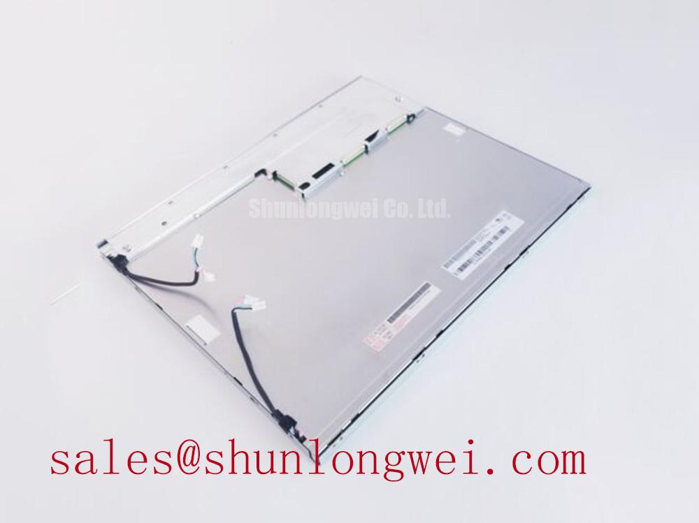
Check the displayed grayscale pattern from the operator’s actual viewing positions and compare tonal inversion, contrast loss, and color shift across the panel before approving the MT506LV4CN for a multi-angle console. The available factory information identifies this unit as an AUO TFT-LCD Active Matrix Color Display Module, but it does not establish a Super-IPS or MVA designation, nor does it provide a verified 85/85/85/85-degree viewing-angle rating in the supplied specification set.
This distinction matters in surgical navigation and ultrasound diagnostic equipment, where several users may view the same image from different positions. A TN replacement can show grayscale inversion or stronger tonal changes away from the normal axis, while IPS and MVA technologies are typically evaluated for wider viewing performance. The panel technology should therefore be matched against the original equipment documentation rather than inferred from the model number.
Use neutral grayscale, skin-tone reference images, and high-contrast test blocks while observing the screen at the intended mechanical installation angle. Record whether dark regions merge, whether bright areas lose separation, and whether fine diagnostic markers change apparent weight. Surface treatment also requires inspection under the final room lighting. An anti-glare finish can reduce reflected fixtures and examination lamps, but excessive diffusion may soften small text or ultrasound annotation lines.
Backlight condition should be evaluated with the specified driver used by the host system. Do not assign a 50,000-hour brightness figure, L70 value, or MTBF curve to this model without the relevant AUO backlight documentation. Measure luminance at the system’s permitted operating condition and repeat the check after thermal stabilization. A replacement panel may have acceptable image geometry yet remain unsuitable if its backlight control, connector position, or optical stack differs from the original assembly.
AUO’s industrial display and embedded systems information provides useful manufacturer-level context for evaluating display technology and optical integration. The final selection remains dependent on the original panel’s interface, mechanical drawing, and display timing requirements.
Eye-Diagram Voltage Margin and Differential Noise-Floor Verification in High-Vibration Bays
Probe the known-good signal path at the panel connector and compare the pixel clock, data transitions, common-mode movement, and displayed noise pattern before changing the display module. Horizontal bands, intermittent pixels, or unstable synchronization may indicate a cable, grounding, timing, or impedance problem rather than a defective panel.
The MT506LV4CN listing supplied for this product does not confirm LVDS or TTL pin assignments, JEIDA or VESA mapping, supply voltage, pixel clock limits, or connector pinout. The system integrator should verify every one of these items from the original panel documentation and host controller records. Do not assume that a physically matching connector has compatible signal polarity or data formatting.
For a differential interface, inspect the complete cable route from controller to panel. Shield termination should follow the equipment’s grounding architecture, with attention to chassis bonding, connector backshells, and the return path around variable-frequency motor drives. Common-mode ferrite suppression may be considered where measured interference persists, but its impedance profile must be checked against the signal edge rate and the complete cable assembly. Adding a component without confirming its effect on the eye diagram can reduce the available timing margin.
Vibration adds a mechanical fault path. Examine the cable for unsupported weight, sharp bending near the connector, and latch movement during equipment operation. A display that works on the bench but drops pixels in service may require simultaneous electrical and mechanical testing. Compare the eye opening and clock stability with the panel stationary and with the enclosure exposed to the actual vibration profile. The correct acceptance limit is determined by the host interface specification and the system’s measured noise environment.
💡 Pro Tip: Keep the differential pair routing balanced and mechanically restrained near the connector, then confirm pixel-clock stability with an oscilloscope instead of judging compatibility from a static image alone.
When a same-size or same-resolution service alternative is being assessed, engineers can review LM195WD1-TLC1 as a separate compatibility candidate, subject to its own electrical and mechanical documentation. It should not be treated as a drop-in replacement until the interface and mounting details are confirmed.
Flashlight Dark-Shadow Optical Diagnostic for Logic and Backlight Fault Isolation
Display a full white image, then illuminate the screen surface at an oblique angle with a flashlight while observing whether image content remains visible in the darkened area. A visible image under the flashlight can indicate that the LCD logic and pixel drive are active while the backlight path requires further testing; no single visual result should be treated as conclusive without checking the controller, supply rails, cable, and backlight driver.
Use a controlled three-pattern bench sequence consisting of primary-color screens, a neutral grayscale pattern, and a full-white field. Look for missing columns, fixed horizontal lines, localized color contamination, or regions that respond to image changes. These observations help separate image-data problems from illumination problems, but they do not prove a particular internal failure mechanism. COG interconnect damage, panel stress, timing faults, and connector instability can produce overlapping symptoms.
Check the backlight enable and dimming signals at the system interface only after identifying their documented electrical definitions. The supplied factory parameters do not confirm whether this particular assembly uses a specific LED driver arrangement, PWM input, analog dimming input, or another control method. The integrator should verify the original panel documentation before applying a replacement control signal.
For a surgical navigation or ultrasound terminal, test image uniformity with the application’s real overlays and measurement graphics. A screen may appear acceptable on a white field while revealing vertical shading or low-level nonuniformity in dark diagnostic imagery. Record the panel temperature and the host brightness setting during the test so that comparisons between the removed unit and replacement remain meaningful.
Cold operation requires a separate review. Liquid-crystal response can change as temperature falls, producing longer transitions, smearing, or delayed gray-level changes. The supplied information does not specify a verified operating temperature range, gray-to-gray response-time curve, heater requirement, or cold-start sequence for MT506LV4CN. A heater strip, enclosure preheating strategy, or display refresh adjustment can be considered only after the original equipment limits and thermal design are known.
Power sequencing also deserves measurement rather than assumption. Monitor the panel supply, enable state, video timing, and backlight activation during startup and shutdown. White-screen behavior, residual images, or intermittent startup may arise from an incorrect order between logic power, reset, video timing, and illumination control. The host controller should be validated against the original panel timing documentation before the replacement is released.
Edge-Lit LED Rail Thermal Dissipation and Optical Stack Preservation
Map the display surface and frame temperature during a sustained bright-image test, concentrating on the edges, connector area, and locations adjacent to the backlight rail. A localized thermal rise can affect luminance uniformity, adhesive interfaces, cable reliability, and long-term optical performance, but the permitted temperature must be taken from the panel and system specifications.
The supplied factory data confirms the product category and TFT-LCD active-matrix construction, but it does not confirm an edge-lit LED architecture, PMMA light-guide material, aluminum rail dimensions, L70/B50 values, or a manufacturer-rated backlight lifetime. These features must not be assigned to the model without an applicable AUO drawing or datasheet. Use the actual panel construction when selecting heat-spreading hardware.
Where a metal spreader is part of the host enclosure, maintain even mechanical support without creating concentrated pressure on the active area or bezel. Thermal interface materials, clips, and brackets should be reviewed for compression, electrical isolation, and service access. The display frame must remain free from twisting forces that could transfer stress into the glass or flexible interconnects during vibration and thermal cycling.
Brightness control should be evaluated with the system’s real image content. Long-duration static menus can produce perceived retention or uneven aging even when the panel remains electrically functional. Designers should consider screen-saver behavior, periodic content movement, brightness limits, and duty-cycle management where the equipment permits these controls. PWM dimming frequency and modulation depth should be selected through a system-level assessment involving camera compatibility, operator comfort, acoustic or optical interference, and the backlight driver specification.
For equipment exposed to cold starts, measure the display during warm-up rather than approving it from a room-temperature image alone. Observe response behavior, uniformity, startup timing, and any residual image while the enclosure follows its intended thermal profile. If the display is integrated into a sealed medical workstation or diagnostic console, airflow, internal heat sources, and the mounting frame should be evaluated together.
Mechanical and reliability decisions can be cross-checked against the engineering discussion in Industrial Display & HMI Solutions. That reference is useful for system-level planning, while the electrical, optical, and mechanical acceptance limits for MT506LV4CN must remain tied to the applicable AUO documentation and the host equipment design.