



Content last revised on September 10, 2026
Flashlight Dark Shadow Optical Diagnostic to Isolate Logic vs. Backlight Failure Modes
Use a known good video source and perform a controlled primary color bench check before removing the panel from its mechanical carrier. Display red, green, blue, black, and white test fields while observing the image from normal viewing distance and at an angle. Record whether the image is absent, unstable, divided, discolored, or visible only under external illumination. This approach separates observations related to the display logic path from observations associated with the illumination system without assigning a single cause too early.
A dark room and a flashlight held at approximately 45 degrees can help identify a faint image when the normal illumination is unavailable. If characters or color fields can be seen beneath the flashlight, the video path may still be producing image information, while the backlight driver, illumination connection, or brightness control path requires further examination. If no meaningful image appears, inspect the input source, panel interface, power sequence, connector seating, and signal activity before drawing conclusions about the glass or driver circuitry.
Line defects require a different observation method. A narrow vertical or horizontal interruption that remains fixed during color changes may justify comparison with a known good signal path and a microscope inspection of the exposed connector region, where permitted by the equipment procedure. A moving image, split field, or intermittent data pattern may also result from connector contact quality, signal integrity, timing configuration, or host controller behavior. Verify the result with an oscilloscope or suitable display test instrument rather than using a visual symptom as a definitive diagnosis.
TTL and LVDS terminology should not be treated as interchangeable during a replacement. The original documentation should identify the electrical interface, data mapping, clock arrangement, and timing requirements for this exact panel. Clock jitter, setup time, and data hold time must be checked across the intended industrial temperature range using the host transmitter and receiver requirements. No TTL or LVDS timing value is included in the verified product information supplied for the M170EP01 V2.
When a failed panel is being replaced in a maintenance store, label every cable before disconnection and compare connector orientation with the replacement documentation. A mechanically similar panel can still be electrically incompatible if its mapping, timing, connector assignment, or backlight control differs. Engineers assessing another display in the same broad size or resolution class can review M185XW01 VE as a separate compatibility reference, but final interchangeability must be established by the system integrator.
Thermal Expansion Clearance Sizing across Heavy Industrial Metal Enclosure Cutouts
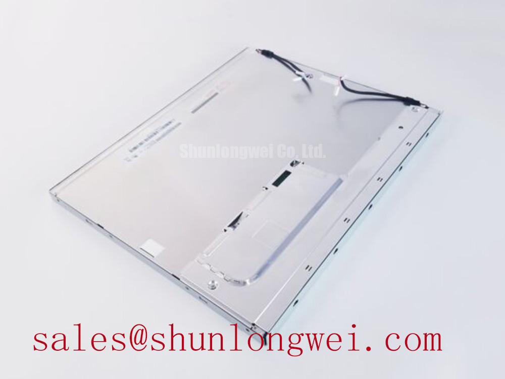
Place the replacement module on a clean, level inspection surface and check the enclosure cutout against the original mechanical drawing before tightening any fastener. The verified information for the M170EP01 V2 does not provide an outer bezel envelope, mounting hole coordinates, glass thickness, or dimensional tolerance. Do not infer those values from the model name or from a visually similar panel. The equipment drawing and the original assembly should control the mechanical evaluation.
In a heavy metal operator station, the bezel should support the panel evenly without forcing the glass or concentrating load at one corner. A cross pattern can help release mechanical stress progressively, but the appropriate fastener size, washer arrangement, gasket compression, and tightening sequence remain system design matters. The supplied engineering reference of 0.35 to 0.45 N·m for M3 fasteners is a Design Consideration only, not an AUO factory specification for this model. The installer should confirm the enclosure manufacturer’s instructions and validate the result by checking for image nonuniformity after thermal cycling.
Local pressure can appear as bright or dark optical nonuniformity, particularly when the panel is clamped against an uneven cutout or a gasket has hardened. Such an observation should be correlated with the fastener pattern, bezel flatness, and temperature condition. It should not automatically be attributed to a light guide plate defect. The M170EP01 V2 factory information provided here does not confirm a specific light guide construction or optical bonding process, so any claim about internal optical materials would be inappropriate.
Thermal expansion clearance should be treated as a measured enclosure problem. Designers should inspect the metal aperture, gasket recovery, cable bend path, and rear clearance while the assembly moves between its specified operating conditions. Condensation risk also deserves attention where a cold panel is installed in a humid cabinet. The enclosure should control moisture ingress and allow the display assembly to reach a stable temperature without trapping water against connectors or the rear electronics.
Backlight ageing must be assessed from the exact panel and driver documentation. A statement such as 50,000 hours to 50 percent brightness cannot be assigned to the M170EP01 V2 from the supplied factory data. LED current, thermal conditions, dimming practice, and driver regulation influence the observed decay curve. If the original equipment record includes a backlight life test, use that record as the reference and verify brightness with an instrument rather than relying on operator perception alone.
Maintenance Note: Inspect the cabinet airflow path and sealing gasket during scheduled service, because blocked ventilation or a deteriorated seal can increase thermal and moisture stress around the display assembly.
20 Pin and 30 Pin Differential LVDS Timing, Pixel Clock and Skew Compensation
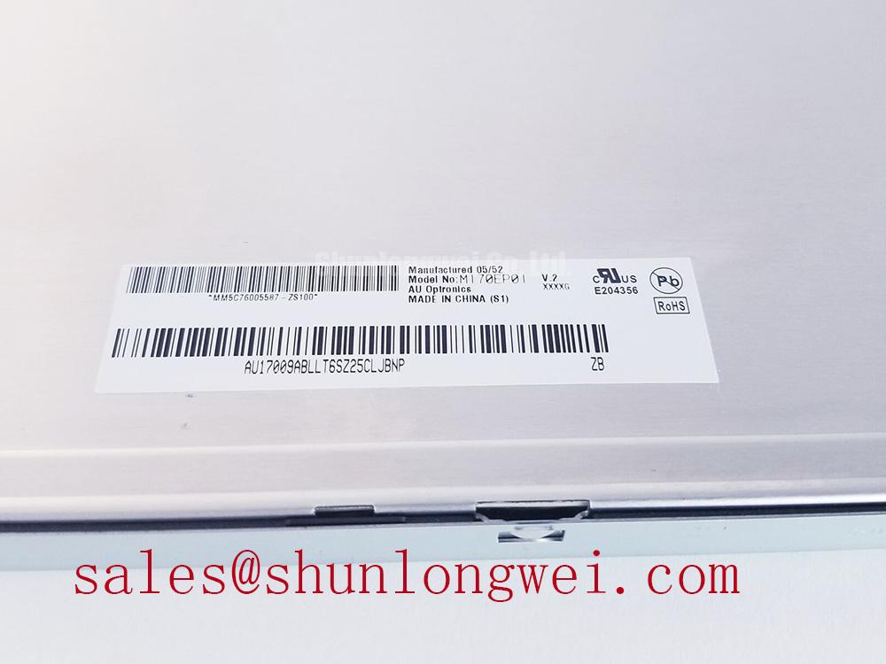
Before connecting the M170EP01 V2, compare the host cable and panel connector with the original assembly record. The verified product information does not state whether this specific version uses a 20 pin or 30 pin connector, nor does it confirm the supply voltage, pixel clock, JEIDA or VESA mapping, or backlight control method. The system integrator should verify the required supply voltage from the original panel documentation. Do not connect a cable solely because its pitch or connector shell appears similar.
Power sequencing is an integration condition rather than a universal panel prescription. The controller should establish the required supply, enable, reset, video, and backlight relationships from the panel documentation and then verify the sequence at the connector with an oscilloscope. The commonly referenced rise interval of 0.5 ms less than t1 less than 10 ms may be used only as a Design Consideration when it is supported by the applicable host and panel timing requirements. It is not an official M170EP01 V2 value in the supplied data.
White screen behavior at startup, residual images during shutdown, or a delayed picture can involve the controller sequence, enable state, cable contact, or power rail behavior. Capture the supply and control signals during both startup and shutdown, then compare them with the known good equipment sequence. This method is more reliable than changing delay values by trial and error. Any timing adjustment should be validated with repeated power cycles at the intended temperature conditions.
For a differential link, the routing principle is to maintain a controlled and continuous return path, minimize unnecessary stubs, and preserve pair symmetry through the connector transition. A 100 ohm differential target is a common Design Consideration for LVDS routing, while the actual impedance requirement must follow the transmitter, receiver, cable, and board stackup documentation. JEIDA or VESA mapping must be confirmed from the original system; selecting one by appearance can produce incorrect colors, split screens, or channel displacement.
PWM dimming should also be treated as a system interface requirement. The supplied M170EP01 V2 information does not confirm a PWM input or a valid dimming frequency range. If the original driver uses PWM, the integrator should verify the permitted frequency, duty cycle behavior, logic level, and enable polarity from the driver documentation. Visual flicker, uneven brightness, or audible driver noise should be measured under the actual control waveform rather than corrected by assuming a generic setting applies to this display.
For IPS, MVA, or other panel technologies, viewing angle color behavior and optical compensation are product specific. The verified data supplied here does not identify the M170EP01 V2 panel mode or provide viewing angle, contrast, or color shift values. Engineers replacing a panel in an HMI should therefore compare the original image at the required operator positions and confirm that the replacement meets the application’s visual acceptance criteria.
Shielded FFC and FPC Flat Flexible Cable Grounding across 360 Degree Connector Shells
Route the display cable with the equipment powered down, supported at its connector, and free from sharp bends or clamp points that can load the contact area. A shielded FFC or FPC arrangement must be verified against the original panel and host design because the M170EP01 V2 factory information supplied here does not define cable construction, shell bonding, connector pin assignment, or grounding topology.
In a cabinet containing variable frequency motor drives, the practical objective is to control common mode current and prevent noisy power wiring from sharing the display signal return path. Designers should keep differential pairs together, provide a deliberate chassis reference at the shield termination, and separate display wiring from high dv and di power conductors where the enclosure permits. A 360 degree shield connection can be considered when it is mechanically supported by the connector and enclosure design, but it must not be assumed to be a feature of this display module.
Ferrite components can reduce conducted interference in some cable arrangements, but their suitability depends on common mode impedance, current, frequency spectrum, and the grounding scheme. Adding a component without measuring the noise path can alter signal quality or create an unwanted return route. Compare the display waveform and image stability before and after any change, using the known good cable path as the reference.
A 100 ohm plus or minus 10 percent differential impedance target and a skew budget no greater than 50 ps are Engineering Recommendations for a high speed LVDS design exercise, not official specifications for the M170EP01 V2. The system engineer must determine whether those targets apply to the actual transmitter, receiver, cable length, and board stackup, then verify them with appropriate signal integrity measurements. Horizontal noise bands, pixel jitter, and intermittent image loss should be investigated at the connector and receiver while the nearby drive operates through its normal switching conditions.
For broader enclosure, sealing, cable, thermal, and HMI integration considerations, consult the Industrial Display and HMI Solutions engineering guide. Its system level guidance should supplement, not replace, the original AUO documentation and the certification requirements of the completed operator station.