

Content last revised on October 10, 2026
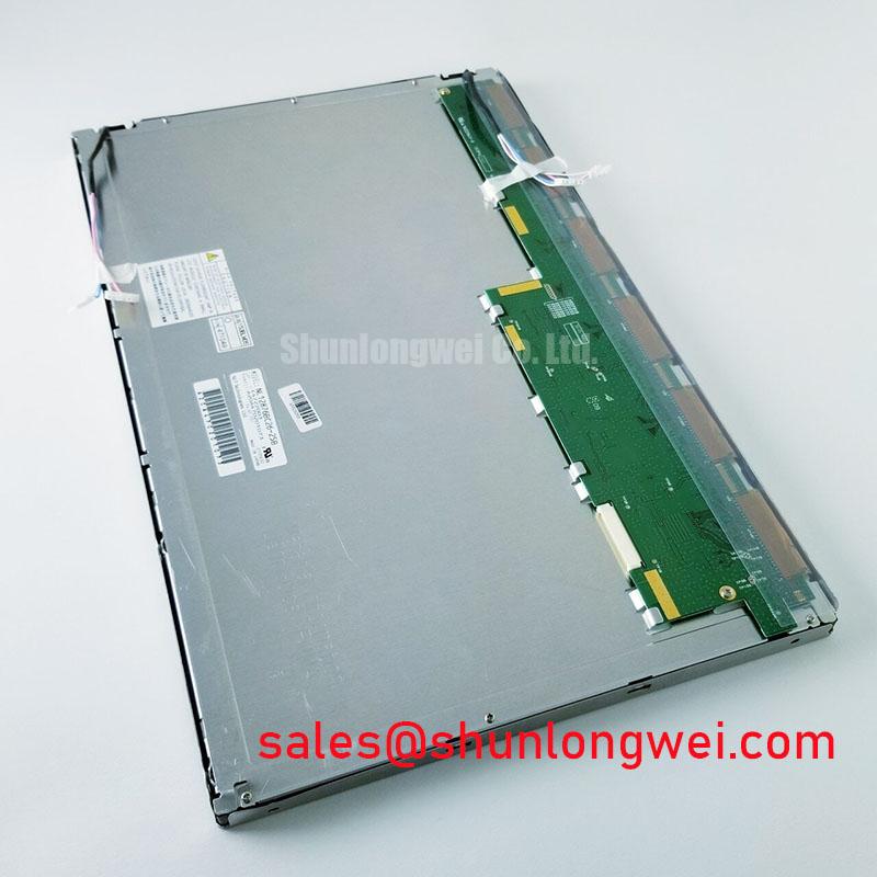
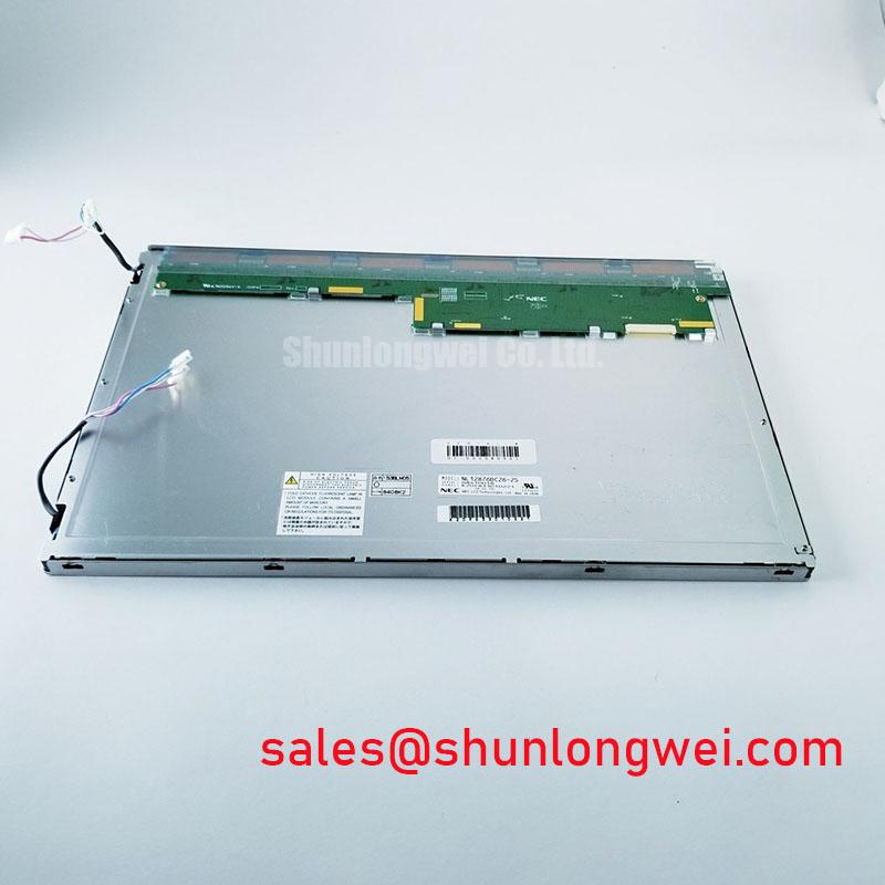
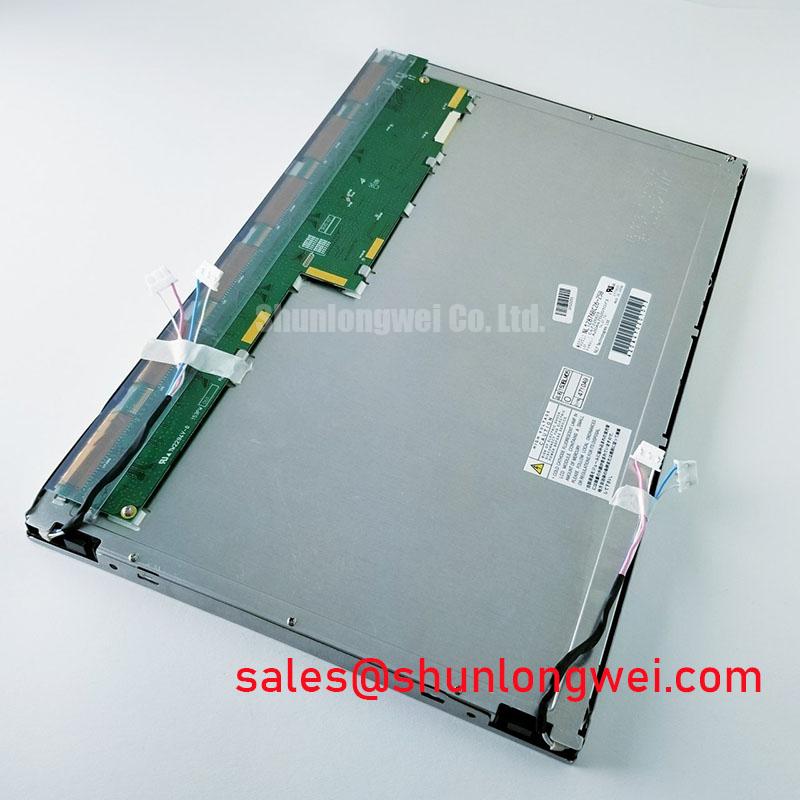
NL12876BC26-22E NEC TFT LCD Industrial HMI Display Module
When a railway cab signalling screen shows a black panel, split image, or intermittent data, isolate the fault at the panel connector before replacing the display. Power down the terminal, inspect the FPC or display cable lock, then compare the logic supply behaviour and video activity with a known working channel. The NL12876BC26-22E is identified as a NEC Industrial Grade LCD/HMI Panel with a TFT LCD Active Matrix Color Display Module construction and a decoded baseline standard form factor.
The supplied product identity does not establish a resolution, active-area dimension, interface voltage, backlight technology, or connector pinout. Those values must not be inferred from the model code. For a railway passenger information system or cab signalling display, the replacement review should therefore begin with the original panel label, controller documentation, cable orientation, and mechanical aperture.
TTL 24-Bit Digital RGB Bus Synchronization and Logic Power Rail Verification
Start the interface investigation by determining whether the host controller is actually providing a compatible digital video bus. The NL12876BC26-22E product identity confirms a TFT colour display module, but it does not by itself confirm TTL RGB, LVDS, JEIDA, VESA mapping, or a particular logic rail. Trace the signal path from the display controller to the panel connector and record the documented power pins, enable signals, pixel clock, horizontal timing, and vertical timing before applying a replacement panel.
For a suspected split-screen image, unstable colour blocks, or a shifted picture, compare the data mapping at the transmitter and receiver rather than changing the supply voltage at random. A JEIDA and VESA mapping mismatch can produce an image with incorrect colour order or visible partitioning even when the panel receives a valid clock. Oscilloscope checks should examine clock integrity, data activity, reset behaviour, and the relationship between power-good and display-enable signals across the complete start-up sequence.
Logic supply rise time is a system integration condition, not an official specification established by the supplied product record. Designers should verify the required rail and its permitted start-up timing from the original NEC panel documentation and the host controller design. The same principle applies to characteristic impedance: controlled routing and a continuous return path can reduce reflections, but the cable construction, connector geometry, transmitter output, and receiver requirements determine the final interface design.
For equipment exposed to a wide industrial temperature range, compare pixel clock stability and data hold behaviour at the actual operating extremes. A display that works on a repair bench may still show intermittent lines when the controller timing margin changes with temperature. If the original assembly is no longer available, NL8048AC19-14F can be reviewed as a separate candidate during a documented form-factor and interface compatibility assessment; it should not be treated as an automatic substitute from model naming alone.
High-Voltage Striking Potential and Secondary Coil Insulation Testing
Before applying high voltage to a suspected backlight circuit, identify whether the installed assembly uses a CCFL inverter or a constant-current LED driver. The supplied baseline for NL12876BC26-22E defines the product as a TFT LCD active matrix colour module, but it does not confirm the backlight source, ignition voltage, PWM range, half-life, or MTBF. These characteristics belong to the complete panel and driver documentation, not to a generic LCD category description.
For an older railway display with a dark image that becomes visible under a service lamp, measure the backlight driver output only with equipment rated for the circuit and with the secondary insulation intact. Arcing, acoustic buzz, repeated ignition attempts, or visible edge glow should lead to a controlled inspection of the inverter, lamp connections, insulation barriers, and return path. Do not substitute a constant-current LED driver for a CCFL inverter without confirming electrical compatibility, connector allocation, current regulation, dimming control, and thermal behaviour.
Cold operation can lengthen liquid-crystal response and make motion or text appear less sharp. This is an engineering consideration for the complete display assembly and enclosure. The system designer should evaluate the panel response, heater strategy if fitted, airflow, and controller refresh behaviour at the real minimum ambient temperature. A separate backlight control module, such as G121XN01-V1, may be relevant to a system-level power-topology review, but its presence does not establish compatibility with this NEC panel.
⚠️ Field Alert: Disconnect the equipment from all power sources and allow the backlight circuit to discharge before removing the display cable or touching the inverter area.
| Evaluation item | NL12876BC26-22E | NL8048AC19-14F review candidate |
|---|---|---|
| Manufacturer | NEC | Confirm from product documentation |
| Product category | Industrial Grade LCD/HMI Panel | Separate LCD compatibility assessment required |
| Display construction | TFT LCD Active Matrix Color Display Module | Confirm from product documentation |
| Interface and backlight | Confirm from the original panel documentation | Confirm from the original panel documentation |
| Replacement decision | Baseline unit for identification | Requires electrical and mechanical validation |
Radiated Emissions Compliance and Backplate Grounding
When a display is installed near a variable-frequency motor drive, first separate video-data interference from a power or backlight fault. Horizontal noise bands, unstable pixels, and intermittent image loss can result from cable routing, return-current control, connector contact, or common-mode coupling. The display module itself must not be described as independently compliant with CISPR Class A or Class B; emissions performance belongs to the complete equipment installation.
A shielded FFC or LVDS cable should be bonded according to the host equipment’s grounding architecture, with the shield termination, panel backplate, controller ground, and cabinet reference treated as one coordinated system. Avoid creating long floating shield sections beside switching nodes. Common-mode ferrite components can be considered where measured interference supports their use, but their impedance profile and placement must be selected from the actual cable and frequency environment.
For brightness control, verify whether the original panel expects analogue dimming, PWM input, enable control, or a dedicated backlight driver. A nominal PWM frequency or duty-cycle range cannot be assigned to this model from the supplied baseline. During commissioning, check brightness linearity, visible flicker, acoustic noise, and image stability while the adjacent drive changes operating state. The Ultimate Guide to Industrial TFT LCD Technology provides additional practical reference for interface, grounding, and display integration reviews.
For broader industry context, engineers can compare display-system practices with Tianma industrial display information and the manufacturer information available through NEC Display Solutions. These references should support system evaluation rather than be treated as a certification statement for an individual panel.
Suppressing Localized Thermal Gradients and Optical Colour Shift
Inspect the display perimeter and mounting frame when colour changes appear near an edge, corner, or backlight zone. Uneven enclosure pressure, blocked ventilation, hot converter components, and direct sunlight can create local thermal gradients that change visual uniformity. The supplied product information does not confirm IPS, MVA, optical bonding, anti-glare coating, contrast ratio, PMMA guide material, LED lifetime, L70, or B50 performance for NL12876BC26-22E, so those features should not be assumed during a retrofit.
Use the original mechanical stack-up as the reference for any replacement review. The bezel, gasket, cable bend radius, rear cover, and mounting points should be checked for interference before the panel is fastened. Excessive local pressure can produce mura, bright spots, or temporary image non-uniformity, while a loose connector can create temperature-sensitive interruptions as the equipment warms.
Where a heat spreader or conductive rail is considered, its contact area, electrical isolation, enclosure airflow, and effect on the panel frame must be assessed by the system engineer. The purpose is to reduce local hot spots without transferring mechanical stress into the glass or flexible cable. For a sunlight-exposed cab display or passenger information terminal, evaluate readability, reflected glare, colour stability, and enclosure temperature together rather than judging optical performance from a brief indoor test.
Long-term static HMI screens also require content-management consideration. Periodic layout changes, controlled brightness, and appropriate screen-idle behaviour may reduce image-retention risk in the complete display system, but no specific burn-in guarantee is established by the supplied product baseline.