


Content last revised on September 30, 2026
Super IPS and MVA Wide Symmetric Viewing Cone for Multi Angle Consoles
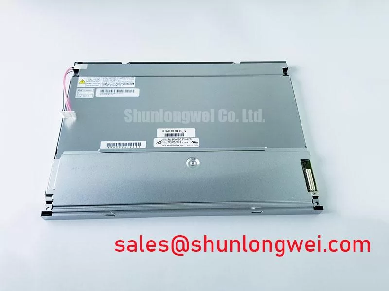
Check the installed panel with a full white, mid grey, and dark test field while viewing it from the operator’s normal working positions, then compare grayscale stability, contrast changes, and visible inversion against a known good display path. The supplied factory data identifies NL8060BC31-42D as an NEC TFT LCD active matrix color display module, but it does not publish a confirmed viewing angle, panel mode, resolution, luminance value, or contrast ratio in the available specification set.
For a CNC operator panel or robot teach pendant, a wide symmetric viewing cone is a practical compatibility issue because the technician may read the display from above, below, or from an offset standing position. The commonly referenced 85°/85°/85°/85° viewing description must be treated as a system evaluation target unless it appears in the original NEC panel documentation for this exact unit. It should not be presented as an official rating for NL8060BC31-42D without that supporting document.
TN, IPS, and MVA technologies can produce different off axis grayscale behavior. A replacement evaluation should therefore use the same image content, backlight condition, viewing distance, and ambient lighting used by the equipment manufacturer. Dark screen fields are particularly useful because grayscale inversion, uneven luminance, and reflected ambient light are easier to identify than on a bright white screen.
Surface treatment also requires physical inspection. An anti glare or anti reflective surface can affect perceived contrast, sharpness, touch response, and cleaning behavior. The original panel’s optical surface should be compared with the replacement under the actual enclosure window. Direct sunlight, overhead factory lighting, and reflections from protective glass can change the operator’s view even when the electrical interface is compatible. A stated contrast target such as greater than 500:1 under 50,000 lux should be treated as an application acceptance criterion only when it is defined by the equipment specification or the panel manufacturer’s documentation.
Signal verification should begin at the display connector and continue toward the timing controller. Confirm that the source uses the same signaling family and pixel arrangement as the original assembly. Do not infer a TTL or LVDS interface from the TFT designation alone. The system integrator should verify the required supply voltage, connector pinout, pixel clock conditions, color mapping, and enable sequence from the original panel documentation.
For LVDS systems, inspect differential waveform symmetry, common mode behavior, and clock quality at the receiving end. For TTL systems, check the individual data lines and clock relationship under the complete operating temperature range. The transmitter must provide adequate setup and hold time for the receiver; the correct margin is determined by the source timing controller, cable construction, connector loading, and panel specification. A replacement that displays an image at room temperature may still require timing validation during cold start, enclosure heating, and rapid load changes.
JEIDA and VESA color mapping should be treated as separate compatibility checks. A mismatch can produce incorrect color ordering or abnormal grayscale transitions while leaving the image apparently stable. Verify red, green, and blue bit positions using a controlled test pattern rather than relying only on a desktop image. Pixel clock polarity, data enable behavior, vertical timing, and horizontal timing should be compared with the original system configuration.
When a same-family alternative is being assessed, the NL6448BC33-71 can be reviewed as a separate display option. It should not be assumed to be a direct substitute until mechanical dimensions, optical stack, connector position, electrical timing, and backlight requirements have been checked against the equipment drawing.
Preventing Localized Light Guide Plate Compression Warp on Dark Screen Fields
Display a uniform dark field and inspect the panel while gently comparing bezel contact, mounting points, and local luminance changes around the perimeter. Any bright patch, dark crescent, or pressure-related mura should be evaluated with the panel unloaded and then with the enclosure assembled, because mechanical stress can be introduced by the frame, window, cable bend, or fastener pattern.
The available factory data does not confirm the internal light guide plate material, optical stack, thickness, or allowable mounting stress for NL8060BC31-42D. Those construction details should not be inferred from the product category. The enclosure designer should instead control the outer bezel envelope using the original mechanical drawing and leave the panel’s active area free from concentrated contact. The display window, gasket, retaining frame, and cable exit must be checked together because a small interference at one edge can distort the panel after final assembly.
Cross pattern fastening is useful for distributing enclosure load, but the correct fastening method remains system dependent. A mounting torque of 0.35 to 0.45 N·m may be used only when it is specified by the relevant equipment drawing or fastener design. It is not an official factory parameter for this model based on the supplied data. The actual limit depends on thread size, bracket material, washer arrangement, screw length, and the load path through the enclosure.
Use a calibrated torque tool during a controlled assembly trial and record the screen condition after each fastening stage. The panel should be observed with the same backlight level used in service. A dark field is valuable because localized optical pressure can remain hidden in bright images. Check the corners, narrow edges, connector side, and areas next to mounting holes. If the defect changes when the frame is loosened, mechanical loading should remain under investigation rather than being assigned immediately to the LCD cell or backlight.
High ambient illumination adds a second inspection variable. Anti glare treatment can reduce mirror reflections, while anti reflective treatment can improve perceived readability when correctly matched to the cover window. The replacement surface must be evaluated with the original protective glass, bezel depth, and viewing direction. Cleaning chemicals, gloves, and repeated wiping can also change the appearance of a surface treatment, so the service procedure should be compatible with the panel and enclosure materials.
Touch operation, where fitted by the host equipment, requires a separate functional check. The supplied product data identifies an LCD/HMI panel category but does not confirm a resistive or capacitive touch layer, touch controller, glove sensitivity, or wet touch performance. The integrator should verify whether the original assembly uses a touch overlay and whether its controller, cover lens, and cable are retained during replacement. Touch accuracy can be affected by bezel pressure even when the displayed image is normal.
When the screen shows a fixed bright or dark region, compare the symptom with the panel outside the enclosure, inspect the gasket and frame for contact marks, and verify that the FPC or FFC is not being pulled sideways. This procedure separates optical loading from signal timing faults without assigning a single cause before measurement.
Shielded FFC and FPC Grounding Across Connector Shells
Probe the display clock and data path at the panel connector while the nearby variable frequency drive and servo system operate through the same duty cycle that produces horizontal bands or pixel jitter. Compare the waveform with the motor drive disabled, then inspect cable routing, shield termination, connector seating, and chassis bonding before changing display timing parameters.
The exact connector definition and cable pinout for NL8060BC31-42D are not included in the supplied factory table. Do not assume that a connector shell is signal ground, protective earth, or a complete 360 degree shield termination. Follow the original NEC wiring document and the equipment schematic. A shield should be connected according to the intended high frequency current path, while signal reference conductors should remain separated from arbitrary chassis bonding points unless the system design specifies otherwise.
LVDS pairs should be routed as controlled differential paths with consistent pair geometry and minimal discontinuity through connectors and transitions. A nominal 100 ohm differential impedance is a common LVDS design reference, not a confirmed specification for this display assembly. The source, cable, connector, and receiver must be evaluated as one channel. Excessive stub length, pair skew, poor return continuity, or an incomplete shield can reduce timing margin and increase susceptibility to common mode interference.
Common mode ferrite components may reduce conducted interference in some installations, but their impedance behavior across frequency and current must match the signal path. They should not be added as a universal remedy because an unsuitable component can increase edge distortion or worsen clock quality. A controlled oscilloscope comparison should cover the display clock, representative data pair, supply rail, and chassis reference while the interfering equipment changes state.
Pixel jitter and horizontal noise bands can also result from power supply disturbance, ground reference movement, connector oxidation, incorrect data mapping, or timing controller instability. Check the display supply at the panel connector during backlight transitions and machine motion. Compare the result with the host equipment’s permitted supply range and the original panel documentation. Do not assign the fault to electromagnetic radiation solely because the symptom appears near a motor drive.
Backlight behavior must be tested separately from image data. The available data confirms a TFT LCD color display module, but it does not confirm LED current, dimming method, backlight connector assignment, brightness rating, or a manufacturer rated lifetime curve. A claim such as 50,000 hours to 50 percent brightness must therefore be sourced from the exact panel or backlight specification before being used in a maintenance calculation. The system integrator should verify whether dimming is analog, PWM, or controlled by a dedicated driver.
The related NL8060BC31-42 may be examined as a same-system display reference when checking driver arrangements, connector conventions, and mechanical documentation. Similar model naming does not establish electrical interchangeability. The original backlight current, connector keying, control logic, and mounting arrangement must be matched independently.
Design Tip: Keep the differential display path away from high current motor conductors and validate pair routing, return continuity, and shield termination with the machine operating at its highest interference condition.
Aluminum Heat Spreader Sizing and Thermal Interface Placement Along Narrow Display Edges
Measure the temperature at the display edges, backlight region, connector area, and enclosure contact points while showing a bright image and operating the equipment at its normal ambient condition. Record the temperature distribution rather than judging heat from a single point, because a narrow edge can develop a local thermal concentration even when the center of the display appears normal.
NL8060BC31-42D is identified in the supplied factory information as a TFT LCD active matrix color display module, but no thermal resistance, permitted surface temperature, power consumption, backlight dissipation, or heat spreader requirement is provided. An aluminum rail should therefore be sized from measured system heat flow and the panel manufacturer’s mechanical and thermal documentation. It should not be described as a factory-required feature of this model.
A heat spreader can improve temperature distribution when it has reliable contact with the intended enclosure surface. The interface must remain electrically and mechanically compatible with the panel. Avoid placing pressure on the active area, polarizer, connector, or flexible cable. A compliant interface layer may be considered where the enclosure design requires tolerance compensation, but its thickness, compression, and thermal performance must be selected from the assembly drawing and verified by trial fitting.
Thermal measurements should include startup, maximum backlight output, dimmed operation, continuous static images, and the heat contribution from adjacent electronics. A CNC operator panel may be installed beside drive electronics, while a robot teach pendant may have a compact sealed housing with limited convection. These are compatibility conditions rather than proof that the display is intended for a particular machine. Enclosure sealing, internal airflow, service access, and cable heat transfer all affect the final result.
Do not attribute yellowing, contrast loss, or luminance decay to one thermal mechanism without inspection. Possible contributors include excessive enclosure temperature, ultraviolet exposure, optical surface aging, backlight current conditions, chemical exposure, and mechanical stress. The supplied information does not confirm PMMA optical components, L70 or B50 lifetime values, or a 50,000 hour operating guarantee. Any such value must come from an exact factory lifetime specification or a documented test source.
Thermal validation should be paired with optical validation. Use the same test image and brightness setting at the beginning and end of the trial, then inspect white uniformity, dark-field mura, color balance, and edge readability. If the display is used behind protective glass, include the glass and gasket in the test because they can change heat retention and surface reflection.
For engineering background on TFT panel interfaces, optical behavior, selection factors, and common integration errors, consult The Ultimate Guide to Industrial TFT LCD Technology. Industry display references such as industrial display solutions from Tianma and the NEC corporate resource can provide broader context, but they do not replace the exact documentation for NL8060BC31-42D.
After thermal and mechanical checks, confirm the panel’s supply sequence, display enable behavior, backlight control, and connector retention during repeated power cycling. The final acceptance record should identify which values came from the factory documentation and which were established by the equipment designer’s own electrical, optical, and thermal tests.