Content last revised on September 10, 2026
Polarizer Durability and Optical Inspection under Direct Industrial Lighting
Inspect the front polarizer under the same lighting conditions found at the machine or console rather than relying only on a bench lamp. Look for scratches, pressure marks, edge lifting, uneven surface reflections, contamination, and local changes in contrast. A panel that appears acceptable in a dim workshop can reveal glare, haze, or viewing-angle limitations when placed near inspection lamps, operating-room lighting, or a bright diagnostic workstation.
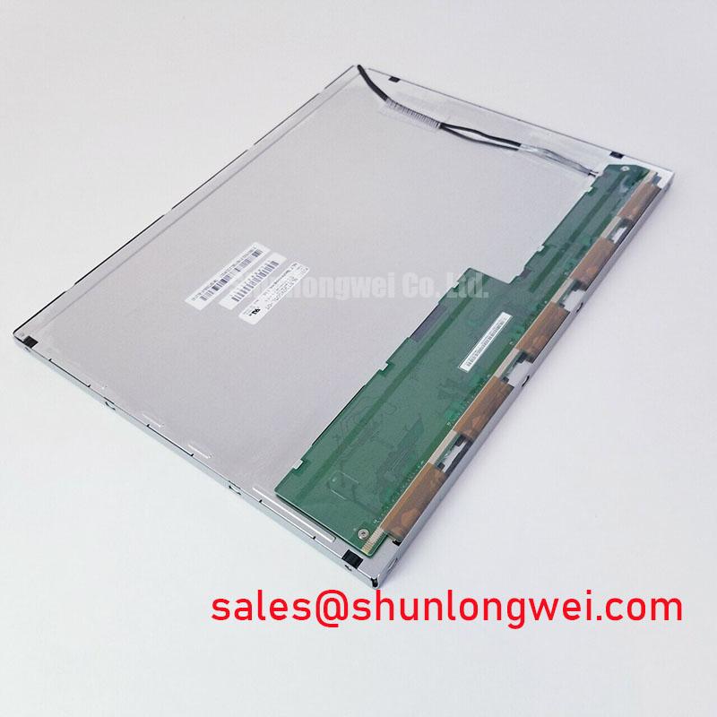
The supplied factory information identifies the unit as a TFT-LCD display module but does not confirm whether its optical mode is TN, IPS, MVA, or another panel technology. It also does not provide a verified viewing cone, optical retardation-film specification, surface treatment, anti-glare etching characteristic, contrast ratio, or luminance value. These properties must not be inferred from the model number. When the original equipment is sensitive to grayscale visibility at an angle, compare the replacement with a known-good panel while viewing diagnostic images from the actual operator position.
Grayscale inversion, loss of shadow detail, and reflected overhead light should be checked separately. A display may show a stable white field while still losing low-level image information in darker regions. For a high-precision surgical navigation or ultrasound diagnostic display, the integrator should evaluate test patterns, text readability, and image uniformity across the complete viewing area. The display module should not be described as suitable for a clinical function until the complete system has completed its own optical, electrical, and regulatory evaluation.
Surface cleaning also requires restraint. Use the cleaning method approved by the equipment manufacturer and avoid applying pressure to the active area. Do not use a sharp tool to remove deposits from the polarizer. If a protective window or touch overlay is fitted in front of the module, inspect the air gap, bonding condition, and frame pressure because external mounting stress can alter the apparent uniformity of the image.
Backlight behavior should be observed during the same inspection. Brightness changes, visible flicker, or an uneven edge may originate in the host backlight driver rather than the LCD cell. The available factory data does not confirm a PWM frequency, duty-cycle response, LED arrangement, or CCFL configuration for this specific model. The system integrator should verify the required backlight architecture from the original panel documentation before connecting any driver.
Digital RGB Bus Synchronization and Logic Power Rail Verification
When the replacement panel remains dark, start at the host board and follow the signal path toward the display connector. Confirm that the controller is enabled, that the cable is fully seated, and that the connector keying and orientation match the original assembly. Inspect for bent contacts, contamination, cracked solder joints, or a cable that is being pulled sideways by the enclosure. A split image, unstable picture, missing color channel, or intermittent display can have several possible causes, so the signal should be compared with a known-good path rather than assigned to one fault without measurement.
The listing identifies the unit as a TFT-LCD module, but the supplied official parameter set does not confirm a TTL RGB interface, LVDS interface, eDP interface, pin assignment, JEIDA mapping, VESA mapping, pixel clock range, clock polarity, data hold time, or transmitter compatibility. Do not connect a controller based on a generic 15-inch panel assumption. The system integrator should verify the complete interface definition from the original NEC documentation or equipment service information.
Logic power must be checked at the panel connector with the system in its normal startup sequence. Confirm the supply rail, enable behavior, ground reference, and voltage stability under load. The original panel documentation should determine the required logic voltage; it should not be guessed from a similar connector or from the voltage printed on the host power board. The rise-time requirement, reset relationship, display-enable timing, and backlight-enable order also remain system-level compatibility items unless explicitly stated in the applicable factory datasheet.
For an LVDS installation, inspect the differential pair routing for unnecessary branches, connector damage, and poor return-current continuity. A nominal characteristic impedance target is a system-board design requirement, not an automatic specification of this display module. The same principle applies to clock jitter, pair skew, termination, and common-mode behavior. Use an oscilloscope and the controller documentation to compare clock and data quality at the panel connector. If the unit uses TTL signaling, evaluate the single-ended reference, logic thresholds, cable length, and ground arrangement instead.
Gamma and T-CON behavior deserve separate attention. A controller can produce a valid-looking test image while incorrect grayscale voltage generation or gamma correction causes posterization, crushed blacks, washed highlights, or a color cast. These functions may be located on the host controller, the panel timing section, or an associated board, depending on the original assembly. Since the supplied product data does not expose a gamma table or T-CON configuration, retain the original controller where possible and verify image output with grayscale ramps, color bars, character patterns, and motion content.
⚠️ Field Alert: Disconnect system power and allow stored energy to discharge before removing or inserting the display cable, because connector contact sequencing can expose signal pins to unwanted electrical stress.
In a servo cabinet or other electrically noisy installation, separate display data cabling from switching nodes and high-current motor conductors where the enclosure permits. This is a design consideration for reducing coupled interference, not an EMC certification claim for the panel itself. The completed equipment must be evaluated against its applicable EMC requirements after installation.
For a same-size or same-resolution replacement assessment, engineers can review NL160120BC27-14 as a separate display option, but its interface, mechanics, optical performance, and timing must be compared independently. It should not be treated as an automatic substitute for NLB150XG01L-01.
Solid-State WLED and Constant-Current Backlight Integration
Before diagnosing a backlight fault, separate the image-generation test from the illumination test. A technician can shine a controlled external light across the front of the panel while the host is running a known image. If picture content is visible, the fault may be within the backlight path, driver enable circuit, protection logic, or cable connection. This observation does not identify a single failed part, so voltage, current behavior, enable timing, and connector continuity should be measured against the equipment documentation.
The official data supplied for this listing does not confirm whether NLB150XG01L-01 uses WLED, CCFL, a dedicated constant-current input, an integrated driver, or an external backlight assembly. Do not connect a LED driver or high-voltage lamp inverter until the original backlight specification has been verified. A driver that appears electrically suitable can still create incorrect startup behavior, overcurrent protection, acoustic noise, visible modulation, or uneven luminance if its control method does not match the panel.
For a WLED system, inspect the constant-current driver output, dimming command, thermal condition, and fault latch behavior. PWM dimming performance should be assessed using the actual host controller and the required brightness range. The supplied factory information does not assign a 1000:1 dimming ratio, a specific PWM frequency, or a duty-cycle linearity specification to this model. These values must be confirmed from the applicable backlight documentation rather than presented as attributes of the LCD module.
For equipment operating near high-frequency switching hardware, route the backlight supply and return as a controlled current loop and keep the wiring away from sensitive signal pairs where practical. The system engineer should verify conducted and radiated noise during startup, brightness changes, and maximum load. Audible buzz can arise from the driver, magnetics, mechanical resonance, or enclosure coupling; it should be traced through measurement rather than automatically attributed to the display panel.
The related NL8048AC19-13KD page may assist engineers reviewing a separate power or display-support option in the same equipment family. Compatibility still depends on the host topology, connector definition, current requirement, control signal, and mechanical arrangement.
Where an LVDS transmitter is used in the display system, differential routing quality can affect image stability during backlight switching and processor activity. Verify termination and pair balance at the system level. A visible artifact that appears only when the backlight changes may involve supply coupling, grounding, timing disturbance, or driver protection behavior, so capture both the data interface and backlight control signals during the event.
Constant Luminance Control and L70 or B50 Reliability Verification
Check luminance uniformity after the panel has reached a stable operating condition and compare the result with the original equipment acceptance criteria. Examine the center, corners, narrow edges, and regions adjacent to the frame. Local darkening or brightening may reflect the optical assembly, backlight distribution, mounting pressure, thermal gradients, or driver channel behavior. The available factory parameters do not provide a verified L70 value, B50 life rating, half-life, MTBF, or guaranteed operating-hour figure for this model.
Do not convert a general LED lifetime statement from another panel into a product-specific reliability claim. Long-term performance depends on drive current, ambient temperature, enclosure airflow, brightness setting, duty cycle, contamination, and mechanical stress. When the panel is evaluated for an ultrasound console or surgical display subsystem, the equipment manufacturer should define the required luminance stability and service interval, then validate the complete assembly under representative conditions.
Thermal inspection is useful during fault isolation. Measure the enclosure and display-frame temperature distribution while the host is displaying a realistic image and operating the backlight at the intended level. Look for localized heating near driver components, cable exits, frame restraints, and narrow display edges. If a heat spreader or conductive frame is added, its contact pressure, insulation clearance, and mechanical tolerance must be reviewed by the system designer. The supplied data does not authorize a particular rail size, thermal interface thickness, or heat-spreader material.
Optical yellowing, haze, and reduced brightness should be treated as observations requiring correlation with temperature, exposure, and operating history. The internal optical materials of this model are not specified in the supplied factory information, so no unverified claim should be made about a particular diffuser, light guide, polarizer film, or polymer composition. Record the display condition, driver settings, ambient conditions, and image pattern used during comparison.
For preventive service, preserve the original bezel geometry and avoid uneven fastener pressure across the panel. Verify that the cable is supported without bending sharply at the connector and that the enclosure does not press against the active area. A replacement assessment is complete only after mechanical fit, power sequencing, interface stability, optical performance, touch response where applicable, and system-level EMC behavior have been checked. Engineers reviewing general TFT-LCD principles can consult The Ultimate Guide to Industrial TFT-LCD Technology alongside the original equipment documentation.