



Content last revised on October 27, 2026
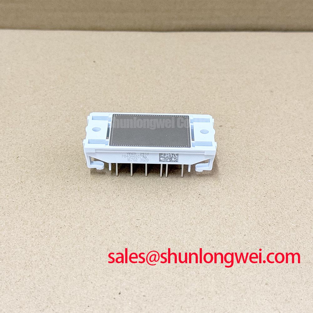
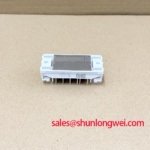
Benchtop Waveform Tuning: Mitigating Stress via Baseplate Thermal Grease Layer Control on P840R4807
I check the mounting surface and the specified thermal interface before interpreting temperature-related waveform changes on a P840R4807 assembly. As a Design Consideration, an uneven thermal interface can complicate comparisons between otherwise identical switching tests. The useful baseline is a documented mounting condition: clean mating surfaces, the specified interface material, consistent fastening and a repeatable case-temperature measurement position.
For a grease-mounted assembly, the objective is continuous contact without excessive material separating the module from the heatsink. Apply the interface material using the qualified assembly process, then inspect coverage during an appropriate trial assembly. Voids, displaced material and uneven transfer patterns warrant investigation. Grease thickness should follow the approved material and mounting instructions rather than a generic thickness target presented as a Vincotech requirement.
Check heatsink flatness and surface damage before attempting to compensate for a contact problem with additional grease. Baseplate curvature, where applicable, must be assessed against the mechanical drawing; it is not a reason to force the housing flat through extra tightening. Follow the specified screw sequence and torque, with progressive fastening where the assembly instructions require it. Keep displaced interface material away from terminals and preserve the clearances established by the equipment design.
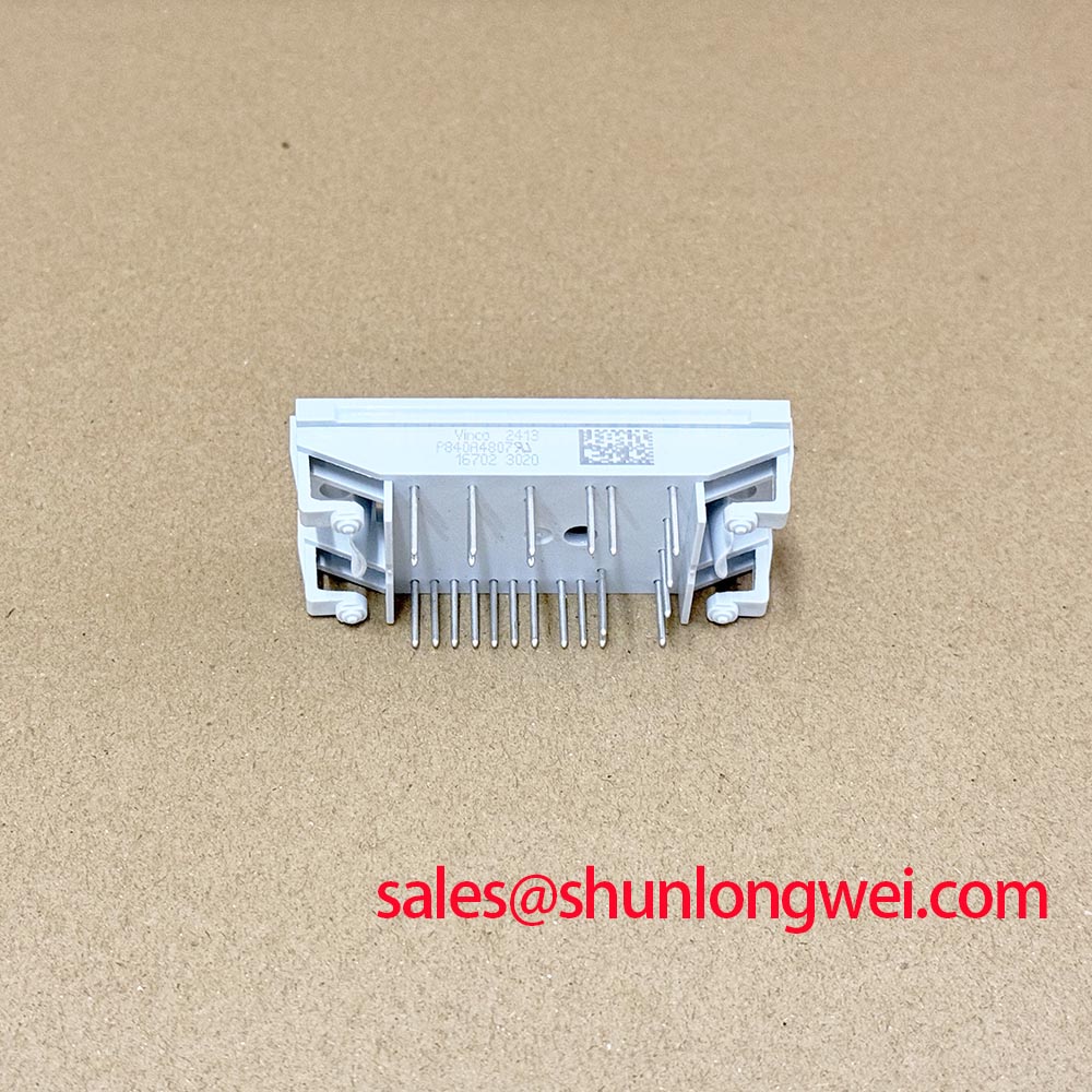
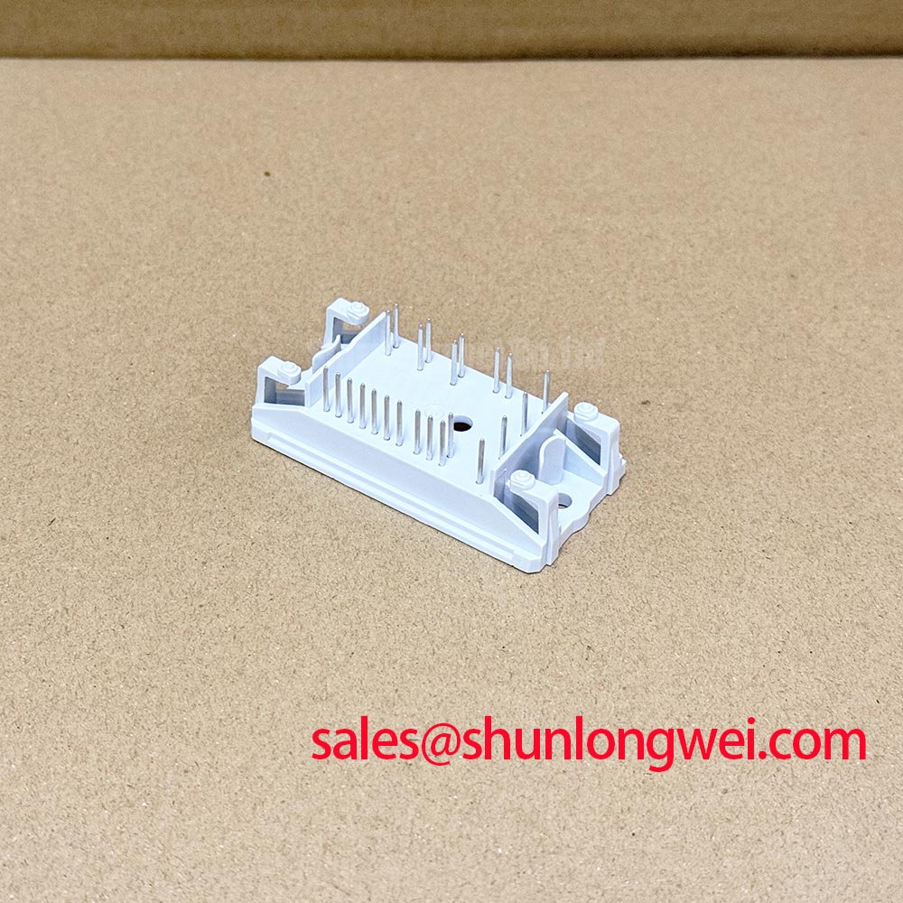
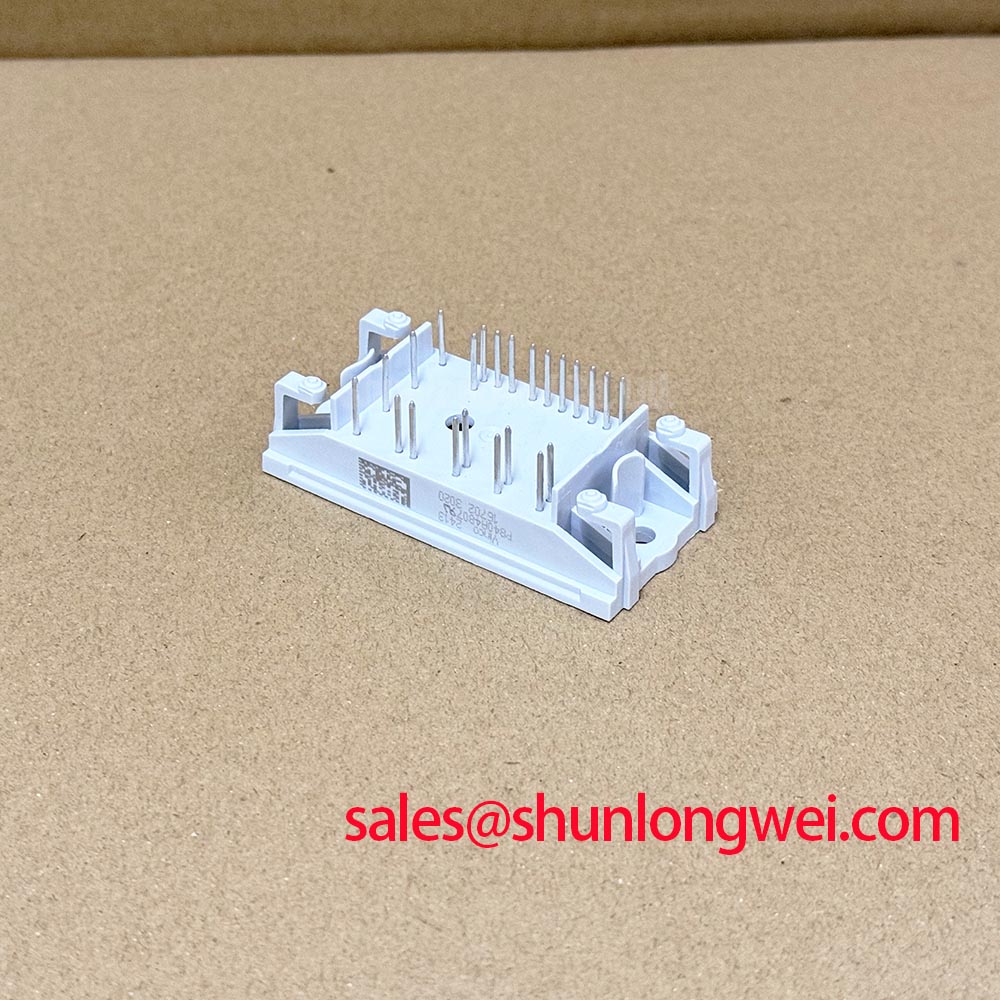
Before energizing the assembly, I map the terminals against the circuit diagram and record cold-state diode-mode readings with a consistent meter polarity. These measurements are comparative screening observations, not proof of blocking capability or switching performance. Unexpected readings call for checking external current paths, terminal identification and the measurement setup before assigning a component fault.
💡 Bench Tip: Discharge the DC link, verify the absence of hazardous voltage and use suitable ESD handling before comparing cold-state readings with a documented reference assembly.
During subsequent powered testing, record coolant or heatsink conditions alongside the electrical traces. A changing thermal boundary can alter measured conduction behavior and obscure the effect of gate-drive adjustments. Insulation checks belong to a separate, approved test procedure using the specified terminal grouping, test voltage and acceptance criteria; a diode-mode reading cannot establish insulation withstand.
P840R4807 Operational Boundaries: Evaluating Drop-In Retrofit: Tuning Turn-On/Turn-Off Limits
Separate turn-on and turn-off behavior when assessing a P840R4807 retrofit rather than copying the previous module’s gate resistors without evaluation. As a Design Consideration, gate resistance influences switching speed, switching energy and interaction with circuit parasitics. The appropriate settings depend on the driver output stage, gate-loop impedance, operating current and the module’s documented switching characteristics.
Capture gate-emitter voltage and collector-emitter voltage with suitable probes and short measurement connections. Compare the switching edges under controlled operating conditions before changing the external gate network. A slower edge can reduce some ringing while increasing switching energy; a faster edge can expose voltage overshoot or unwanted gate coupling. Select adjustments through measured trade-offs within the approved operating envelope, not from waveform appearance alone.
For purchasing and maintenance records, keep the P840R4807 product reference attached to the equipment-specific terminal map and mechanical drawing. When a comparison list includes CM300HA-24E, treat it as a separate compatibility assessment, not an established substitute. Internal circuit configuration, mounting geometry, driver requirements and protection coordination must all match the application requirements before interchangeability can be established.
Parallel operation requires a separate electrical and thermal assessment. A positive temperature coefficient of collector-emitter saturation voltage can assist static sharing within the operating region where that characteristic is documented; it must not be assumed for this model from its category alone. Symmetrical power paths, comparable thermal conditions and balanced gate connections remain important because static sharing does not establish equal switching currents.
When evaluating compatibility with a heavy-duty variable-frequency AC motor drive, distinguish power-stage behavior from control-loop behavior. The Clarke transformation in motor drives describes how phase quantities are represented for control calculations; it does not establish module current capability or protection limits. Investigate measured phase imbalance against both the sensing chain and the power circuit.
Also examine the gate-driver isolation path during fast transitions. As a Design Consideration, an optocoupler or digital isolator must maintain correct signaling under the common-mode transients produced by the assembled converter. Check driver supply integrity, return routing and output behavior together. An unexpected gate pulse can have several origins, so correlate it with the isolation input and supply traces before changing components.
P840R4807 Circuit Protection & Reliability: Calibrating Transient Thermal Impedance
Evaluate pulsed overloads against the junction-to-case transient thermal impedance associated with the exact module configuration. Case temperature alone does not reveal the instantaneous junction peak. As an Engineering Calculation, a rectangular loss pulse produces a junction-to-case temperature rise obtained by multiplying pulse power by the transient thermal impedance at that pulse duration, under the boundary conditions of the thermal model.
For repeated or irregular pulses, use the manufacturer-supported thermal network with the measured or calculated loss waveform. A multi-RC representation describes thermal response over different time scales; its coefficients should come from the applicable model rather than being invented from a steady-state thermal-resistance value. Include the actual case-temperature history and distinguish internal thermal response from the external interface and heatsink response.
Protection assessment should connect that thermal analysis to the driver’s fault sequence. Desaturation detection observes collector-emitter behavior during commanded conduction, but its threshold, blanking and response must be coordinated with the documented short-circuit operating limits. Soft turn-off can reduce interruption stress while extending the fault-current decay interval. Validate the complete sequence rather than assuming that detection alone establishes short-circuit protection.
Semiconductor fuse coordination also requires more than comparing nominal current ratings. Evaluate fuse clearing behavior and let-through energy against the documented withstand of each affected circuit element and the available fault current. An I²t comparison does not independently establish containment or module survival. Where a diode surge rating, ITSM, is specified, retain its waveform, initial temperature and recovery conditions when assessing an overload.
The discussion in Unlocking Efficiency in Industrial Drives offers background for switching-loss and thermal-margin assessment, not evidence that P840R4807 uses that semiconductor technology. Close the bench assessment by checking the recorded peak-temperature estimate and fault interruption traces against the applicable device limits, then preserve the mounting condition, driver settings and test conditions with the equipment service record.