
Content last revised on October 28, 2026
- Verify terminal-to-heatsink clearance and check cold-state DC-link busbar resistance with a calibrated Kelvin 4-wire milliohmmeter prior to energizing main power.
- Inspect driver stage optocoupler and gate power supplies under low-voltage bench power to ensure clean asymmetric output voltages (+15 V / -8 V) on all inverter switching channels.
- Examine the ceramic DBC substrate base and mounting baseplate plane for mechanical flatness tolerances within 50 µm before applying thermal grease.
- Review the trip timing curve of upstream high-speed semiconductor fuses relative to module sub-cycle surge let-through ratings to prevent catastrophic package rupture during dead-short fault scenarios.
Field Diagnostics & Commissioning: High-Speed Semiconductor Fuse I2t Melting in P849A4807 Topologies
Field commissioning of high-density power stages utilizing the P849A4807 flowPIM / flowPACK topology demands tight coordination between upstream circuit protection and power semiconductor withstand capabilities. When integrating this module into industrial platforms such as electric material handling and forklift low-voltage traction drives, DC-link bridge shoot-through or ground faults impose high di/dt fault currents across the DC bus. Rapid disconnection is essential to prevent casing explosion and plasma discharge. System engineers must correlate the total clearing I2t of high-speed semiconductor protection fuses with the module sub-cycle thermal surge rating (Official Datasheet Specification). If the clearing I2t of the fuse exceeds the maximum let-through energy rating of the internal silicon dies and bond wires, the internal metallization vaporizes, generating extreme internal pressure that compromises the flow package integrity.
When selecting protective fuses for high-availability systems, field technicians must balance continuous current carry capability against sub-cycle clearing speed. The fuse melting I2t must remain sufficiently high to withstand motor inrush, inductive magnetization currents, and transient vehicle acceleration loads without nuisance trips, yet its total clearing I2t at rated DC-link operating voltage must sit strictly below the withstand limit of the module internal semiconductor elements. In power architectures incorporating front-end rectifiers such as the DPF1000, short-circuit current paths flow directly through input bridges and intermediate links. The clearing action must complete during the sub-transient period, quenching electrical arcs before collateral structural damage spreads to the gate driver circuit or cooling blocks.
During catastrophic fault investigations where a module has experienced an uncontained failure, field diagnostics center on determining whether the failure originated from thermal runaway or an unmitigated secondary current surge following gate breakdown. In troubleshooting benches, engineers evaluate the physical fuse link alongside terminal continuity across the high-side and low-side switch pairs. Replacing blown fuses with generic industrial distribution fuses (such as Class gG or gL) represents a critical field error; generic utility fuses exhibit prolonged arcing durations that provide zero protection for sensitive IGBT silicon. Field replacements must maintain exact semiconductor-grade fuse profiles (Class aR or gR) to preserve the rapid energy-clearing envelope mandated by modern power converters.
In low-voltage industrial vehicle traction units, compact physical layout often constraints clearance rules. Busbar inductance between the energy storage bank, the fuse block, and the module power terminals directly shapes the peak transient voltage during current interruption. When the fuse element melts and creates an internal clearing arc, the sudden drop in di/dt generates an inductive kickback across parasitic inductances. Layout engineers must position high-speed fuses in close proximity to the DC terminals while maintaining creepage and clearance distances compliant with industrial isolation standards. To benchmark gate drive survival margins and analyze overvoltage limits during extreme trip events, review standard industry verification procedures detailed in the IGBT Design & Integration guide.
P849A4807 Thermal-Electrical Optimization: Thermal Stress Monitoring across High-Curr Practical Tuning
Operating reliability under continuous full-load duty cycles hinges on minimizing interface thermal resistance and managing terminal bolted joint contact resistances. On traction inverter stages and auxiliary lift pumps, continuous RMS currents generate localized thermal gradients at connection terminals. A contact resistance exceeding 10 µΩ across terminal bus connections creates localized hot spots, driving conductor temperatures well beyond nominal thermal limits. Field maintenance personnel should utilize a digital micro-ohmmeter across all bus connections during routine commissioning and apply thermographic imaging under steady-state operating loads to detect asymmetric thermal profiles before joint relaxation leads to thermal runaway.
⚠️ Field Alert: Adhere strictly to the manufacturer-specified screw torque ratings (General Industry Design Consideration for flow packages typically 2.0 to 2.5 N·m) and apply a uniform thermal grease layer of 50 to 100 µm thickness to prevent mechanical substrate cracking and dry thermal voids.
Thermal optimization also requires managing switching transients and freewheeling diode dynamics. When the P849A4807 commutates inductive currents, the reverse recovery characteristics of the integrated freewheeling diodes interact with circuit stray inductances. Fast diode turn-off can trigger snappiness, exciting parasitic resonances that manifest as high-frequency radiated electromagnetic interference (EMI) and localized micro-oscillations. Tuning the gate turn-on resistance (R_G,on) serves as a primary knob for controlling diode peak reverse recovery current (I_rrm) and reverse recovery di/dt, trading off small switching loss increments for substantial reductions in voltage stress across the diode junction.
In multi-axis motion controls and warehouse logistics drives, system designers occasionally audit baseline variants such as the P084A2004 to evaluate thermal performance differences across diverse module topologies and internal silicon technologies. When thermal runaway occurs without an apparent load overcurrent, check for uneven thermal interface material (TIM) application or uneven screw tensioning across the module base. If the center of the module bows away from the heatsink, thermal contact drops precipitously, inducing junction temperature spikes (T_j) that accelerate silicon degradation during acceleration or regenerative braking phases.
Thermographic field inspection protocols should be executed while running the equipment at continuous rated torque. A properly mounted module exhibits a smooth thermal gradient spreading from the center of the semiconductor junctions outward toward the baseplate edges. Hot spots isolated exclusively around an individual phase lead or terminal bolt indicate mechanical loosening, galvanic oxidation, or uneven surface planarity. Remediating these connections requires disassembling the terminal stack, cleaning copper mating surfaces with an approved electrical contact solvent, re-applying a calibrated torque wrench, and confirming micro-ohm symmetry across all three output phases.
P849A4807 Circuit Protection & Reliability: Calibrating Output Sinusoidal Filter vs dv/dt Reactor
Long cable runs connecting inverter modules to AC induction or permanent magnet synchronous motors introduce critical transmission line dynamics. Steep switching edges generated by the fast IGBT switches (dv/dt rates frequently exceeding several kV/µs) propagate along motor leads, encountering an open-circuit impedance boundary at the motor terminals. This impedance mismatch reflects high-frequency voltage waves, resulting in peak terminal spikes reaching up to twice the nominal DC-link voltage (2x V_DC). Over continuous operating cycles, these transient overvoltages cause partial discharge, erode inter-turn stator winding insulation, and induce shaft voltages that drive EDM bearing fluting.
To evaluate phase current vector dynamics and harmonic components under complex modulation schemes, field engineers routinely employ the Park Transformation (Direct-Quadrature-Zero dq0 Transformation) to translate stationary reference frame stator variables into a rotating reference frame, separating torque-producing current vectors from high-frequency distortion components. Suppressing these transmission line phenomena requires either an output dv/dt reactor or a comprehensive LC sinusoidal filter. A standard dv/dt choke, positioned directly at the inverter output terminals, limits voltage rise times to levels acceptable for standard motor insulation (typically reducing dv/dt below 1000 V/µs). This configuration dampens voltage reflections across moderate cable lengths, preserving system efficiency with minimal physical footprint.
For applications with unshielded leads, extreme cable runs, or sensitive electrical environments, a full sinusoidal filter provides a superior engineering solution. Sinusoidal filters integrate series inductors and shunt capacitors configured as a low-pass network with a cutoff frequency situated comfortably above the fundamental motor frequency but well below the inverter carrier switching frequency. This converts the pulsed PWM square-wave output into a smooth sinusoidal phase-to-phase voltage, eliminating motor insulation stress and neutralizing common-mode current leakage through vehicle chassis grounds.
Designing and calibrating output magnetic components requires careful evaluation of inductive core forces under peak saturation currents. In high-current reactors, dynamic mechanical forces generated within the magnetic core structure can be modeled via the Maxwell Stress Tensor in High Magnetic Field Inductor Engineering, which highlights the risk of mechanical core humming, acoustic vibration, and insulation degradation under high ripple currents. When sizing chokes for the P849A4807, engineers must confirm that the inductor does not enter deep magnetic saturation during peak motor torque delivery. Core saturation causes inductance to collapse rapidly, stripping away dv/dt suppression and exposing the inverter bridge to unattenuated high-frequency capacitive displacement currents.
| Filter Architecture | dv/dt Reduction Capability | Motor Terminal Voltage Peaks | Primary Application Scope |
|---|---|---|---|
| Standard dv/dt Choke | Attenuates edges down to <1000 V/µs (Engineering Recommendation) | Limits reflection spikes to ~1.3–1.5x V_DC | Cable runs up to 30–50 m; general industrial motor drives |
| Full Sinusoidal (LC) Filter | Completely converts PWM to sinusoidal (<50 V/µs) | Eliminates reflections; smooth waveform ~1.0x V_DC | Cable runs >100 m; standard non-inverter-duty motors; legacy retrofits |
| Common-Mode Core Rings | Minimal differential dv/dt attenuation | No change to differential phase-to-phase reflection | Bearing current mitigation; chassis grounding noise suppression |
Field verification requires probing phase-to-phase and phase-to-ground terminals directly at the motor junction box using high-voltage differential probes and an isolated oscilloscope. If ringing frequencies correspond to the characteristic transmission line propagation delay of the cable harness, adding passive damping resistors across the filter capacitors or increasing the gate turn-off resistance (R_G,off) within safe dead-time boundaries dampens reflection modes, ensuring stable operation throughout dynamic load changes.
[-----more-----]
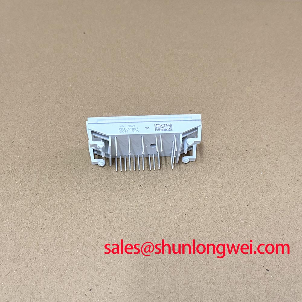
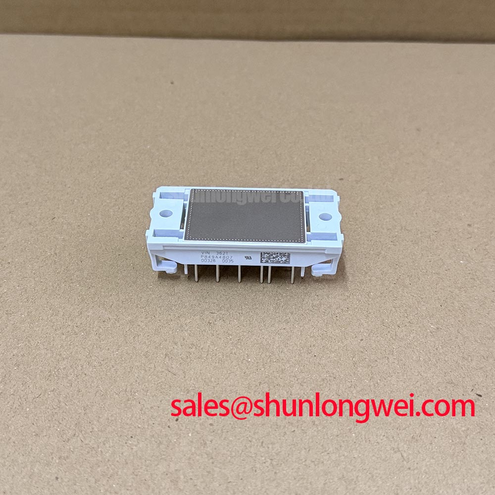
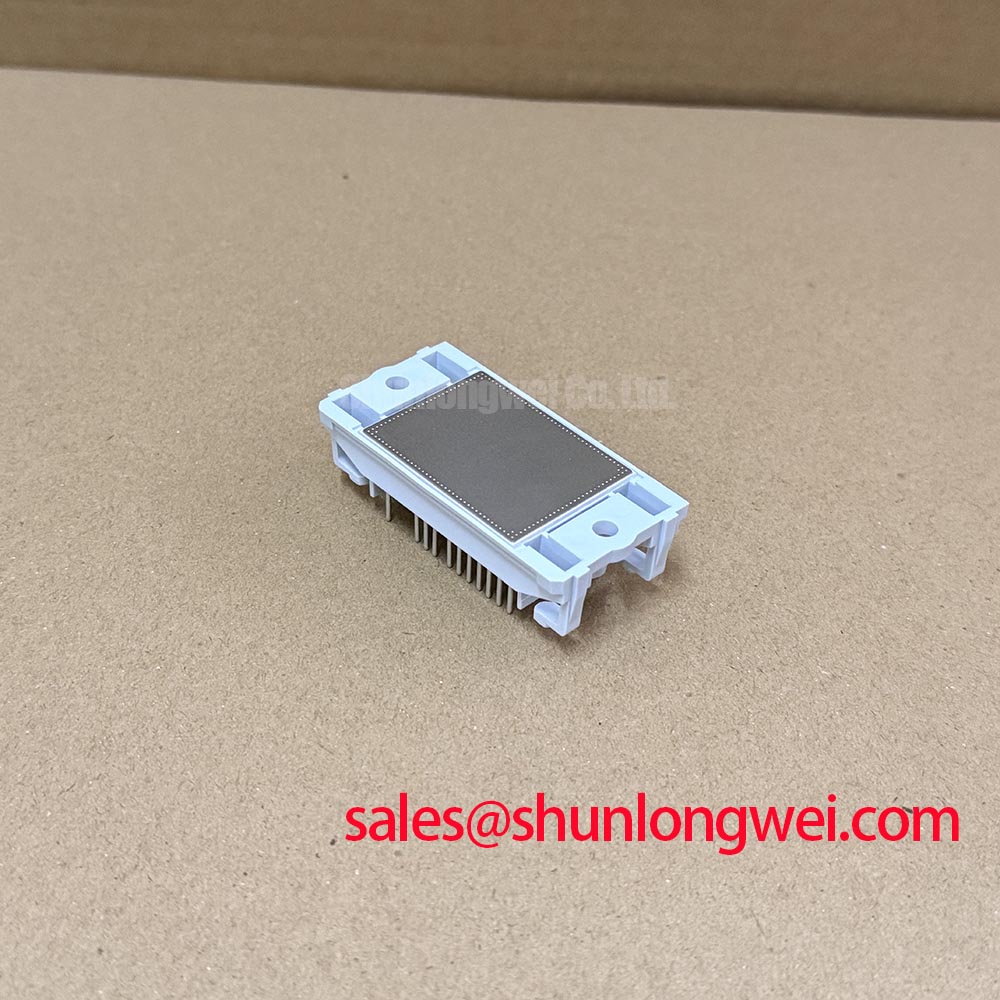
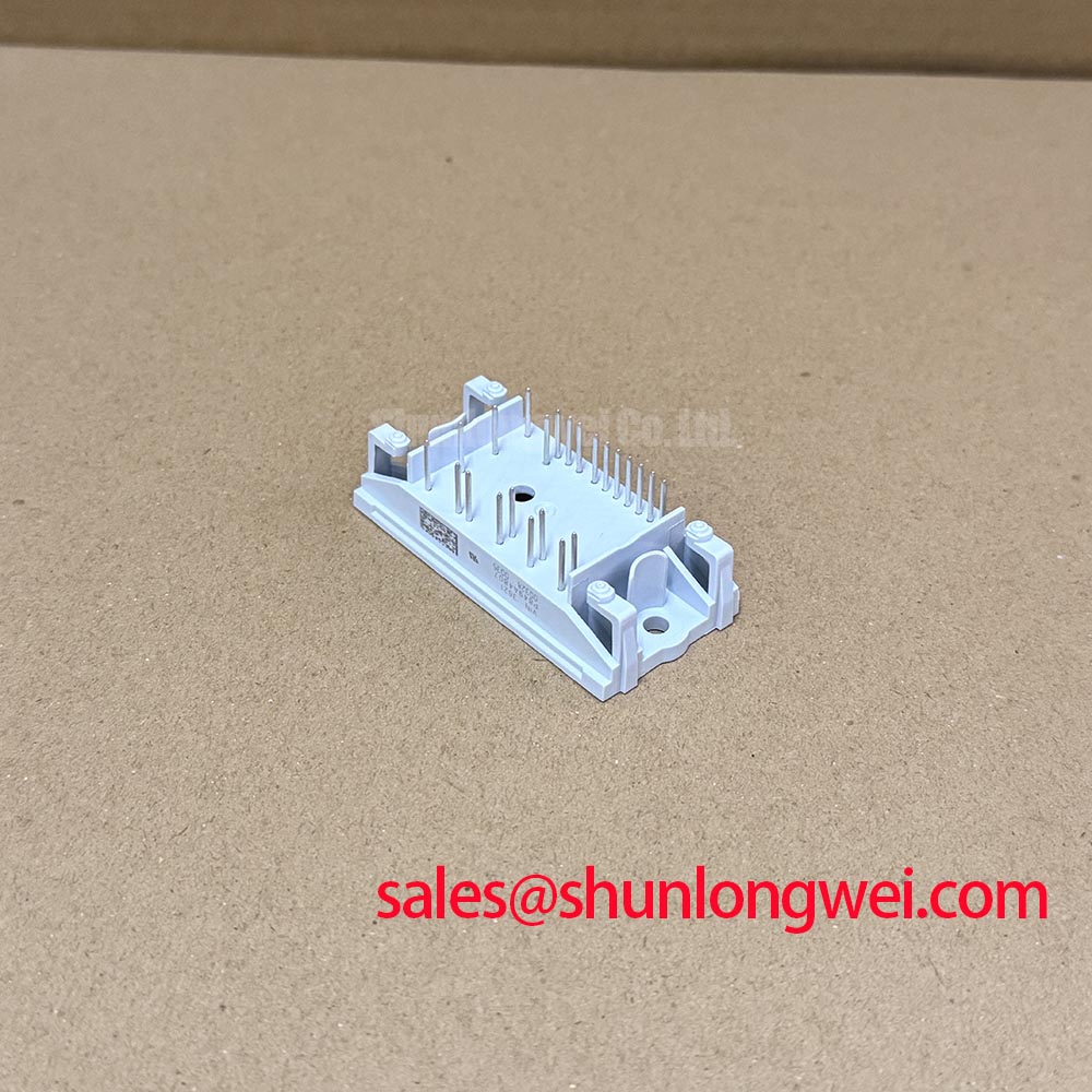
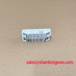
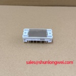
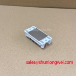
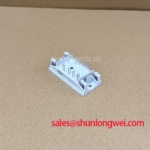
P849A4807 Vincotech Industrial IGBT Module
3
P849A4807 Vincotech IGBT Module | Industrial Traction
Source original P849A4807 by Vincotech for Electric Material Handling & Forklift Low-Voltage Traction. Reliable industrial duty ratings. Fast global dispatch.