Content last revised on September 19, 2026
Field Diagnostics and Commissioning for High Peak Operation with PC2508
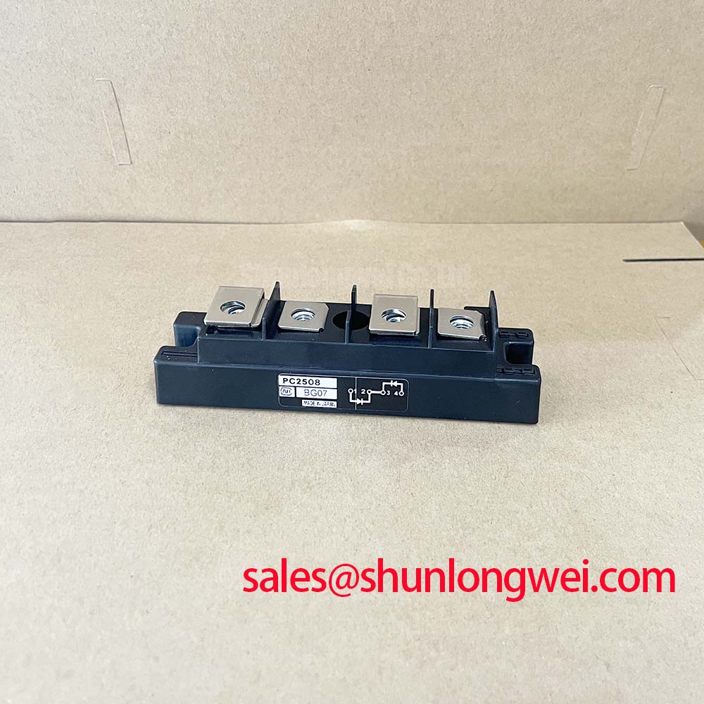
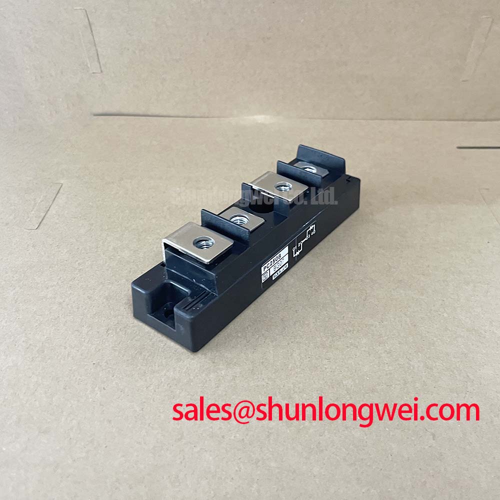
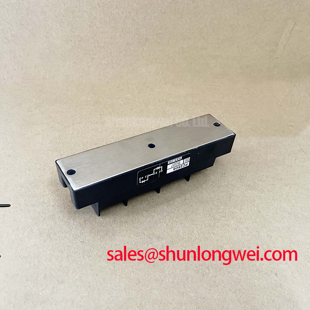
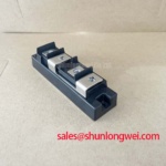
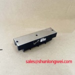
Begin a service inspection by isolating the equipment, recording the nameplate ratings, and checking the module body, terminals, mounting surface, and surrounding wiring for visible thermal or mechanical damage. The PC2508 from Nihon Inter (NIEC) is identified in the supplied manufacturer data as a 600.0 V, 25.0 A isolated power module. These are the confirmed product ratings available for this page and should be compared with the original furnace or power-converter documentation before energizing a replacement.
For a medium-frequency induction melting or hardening furnace, the module may be evaluated within a controlled rectifier or power-conversion assembly, but the complete circuit topology must be confirmed from the equipment schematic. A product category of thyristor / diode module does not, by itself, establish the internal terminal arrangement, surge-current rating, gate characteristics, reverse-recovery data, or fuse coordination value. Engineers should therefore avoid assigning an ITSM, I2t, gate trigger current, or junction-temperature limit unless that value is present in the applicable PC2508 technical documentation.
Commissioning should start with a cold visual inspection and continuity checks performed with the module disconnected from all external circuits. Compare the measured terminal relationships with a known-good unit or the approved circuit drawing rather than relying on an assumed pinout. Any unexpected low-resistance path should be investigated together with the connected snubber, resistor, transformer, and measurement leads, since an in-circuit reading may not represent the semiconductor junction alone.
High peak current operation requires coordination between the semiconductor, the semiconductor fuse, the busbar, and the control sequence. The correct fuse must be selected from a verified coordination table that includes the module’s permitted surge and I2t information. The supplied product data does not provide those values, so the protection study remains a system-level engineering task. During a controlled test, record line current, conduction timing, heat-sink temperature, and the voltage waveform at the module terminals. The objective is to confirm that the operating waveform remains inside the documented voltage and current boundaries without treating a single successful start as proof of long-term reliability.
Check the mounting face for contamination, uneven contact, or hardened thermal interface material before fitting the module to its heat sink. The installation torque must follow the PC2508 mechanical documentation or the equipment manufacturer’s approved work instruction. If no model-specific torque value is available, the responsible engineer should obtain it rather than substitute a guessed value. Uneven pressure can affect thermal transfer and can also place mechanical stress on an isolated module package.
For reference during topology review, engineers can compare the neutral product information for PGH50N16, but a comparison model is not an automatic replacement recommendation. Voltage class, current duty, internal circuit arrangement, gate requirements, isolation characteristics, dimensions, and mounting details must all be checked against the original equipment requirements.
PC2508 Circuit Protection and Reliability with MOV and Input Surge Coordination
Protection work should begin at the incoming power path and proceed toward the semiconductor terminals. A primary spark gap, fuse, metal oxide varistor, line reactor, and RC network each address different parts of a transient event. Their placement and energy ratings must be evaluated as a coordinated system rather than selected from the PC2508’s nominal voltage and current ratings alone.
The confirmed 600.0 V voltage rating is an important product boundary, but it is not a complete MOV selection instruction. A varistor’s continuous operating voltage, clamping behavior, pulse-energy capability, repetition duty, and connection to protective earth must be matched to the actual line voltage and transient environment. Designers should verify the maximum recurring voltage at the module terminals, including supply tolerance and abnormal operating conditions, before specifying the MOV. The device should not be selected simply because its catalog voltage appears close to 600 V.
IEC 61000-4-5 test conditions can be useful when defining a system immunity test, but compliance of the assembled furnace or converter cannot be inferred from the presence of a PC2508 or an individual MOV. Surge-current paths, enclosure bonding, cable routing, protective-device coordination, and test configuration all influence the result. A qualified system engineer should define the applicable test level and confirm the finished equipment against the required standard.
An RC snubber may be placed across a switching or rectifying path to control ringing and unwanted voltage rise, but its resistor, capacitor, pulse rating, insulation rating, and heat dissipation must be selected from measured waveforms and the actual circuit topology. The PC2508 data supplied here does not state an approved snubber value. Use an oscilloscope with a suitable high-voltage differential probe to examine the module terminals during switching and commutation, then validate the proposed network under the highest relevant load and line condition.
Fuse coordination is equally important. The 25.0 A rating identifies the stated current class of the PC2508; it does not define the acceptable fuse current, fuse clearing time, or short-circuit withstand of the complete assembly. The fuse I2t must be compared with the semiconductor’s documented I2t and surge capability and the prospective fault current of the installation. If the manufacturer’s fuse coordination table is unavailable, the system designer should obtain the original protection data or conduct a properly controlled engineering assessment.
Terminal workmanship deserves the same attention as the protection components. Clean contact surfaces, correctly supported conductors, and strain relief reduce the possibility of loose connections and localized heating. Terminal dimensions, permissible conductor size, and tightening torque should be taken from the relevant PC2508 drawing or the equipment service manual. Do not infer terminal polarity or gate connections from the package outline alone.
⚠️ Maintenance Note: During scheduled service, clean the heat-sink air path and check contact temperature under a repeatable load before returning the furnace to unattended operation.
Transient Dynamics and Electrical Design: Reverse Recovery Evaluation
When the PC2508 is used in a converter involving diode commutation, reverse-recovery behavior should be verified from the exact technical data for the installed version. The supplied specifications confirm the 600.0 V and 25.0 A ratings, but they do not confirm reverse-recovery peak current, recovery time, softness factor, junction capacitance, or switching-loss curves. Those parameters must not be estimated from the model number.
In a medium-frequency induction power supply, commutation can create voltage overshoot and high-frequency current movement through stray inductance. The practical diagnostic task is to observe the voltage across the module and the current in the commutation path at the intended operating frequency. Use measurement equipment with bandwidth and insulation appropriate to the circuit. Probe placement should minimize the measurement loop, and the waveform should be compared with the manufacturer’s stated test conditions when such curves are available.
A hard recovery waveform may increase ringing and electromagnetic coupling, while a soft recovery device may behave differently under temperature, current, and reverse-voltage changes. These are general design considerations, not confirmed characteristics of the PC2508. The system engineer should determine whether the installed module’s reverse-recovery behavior is compatible with the transformer, reactor, busbar, snubber, and control timing. Changes to gate timing or commutation components should be validated at the lowest and highest intended load rather than judged from a no-load test.
The surrounding wiring is part of the transient path. Keep the high-current loop compact in accordance with the converter layout requirements, separate sensitive gate or control wiring from high di/dt conductors, and verify protective-earth bonding through the enclosure design. The exact clearance and creepage requirements depend on working voltage, pollution environment, insulation system, and applicable equipment standard. They should be taken from the finished-equipment safety assessment, not invented from the module’s current rating.
External technical references can help establish a disciplined measurement method. The Semikron-Danfoss Power Electronics and Modules Official Hub provides industry reference material for power-module application work, while the Semikron MiniSKiiP power module resource offers additional context on module integration. These references do not constitute PC2508 manufacturer specifications.
For furnace troubleshooting, capture the waveform before changing several components at once. Check whether the abnormal signal is present at the module terminals, the control output, or only at a remote measurement point. A distorted trace may result from probe connection, grounding, control timing, wiring impedance, or a component fault. Correlating voltage, current, trigger timing, and temperature provides a more reliable basis for deciding whether the PC2508 or another part of the commutation network requires further examination.
Snubber and Saturable Reactor Evaluation for PC2508 Converter Topologies
RC snubber and series-reactor work should be treated as a measured commissioning exercise. The purpose is to limit unwanted voltage ringing, suppress false triggering, and control current transition stress without creating excessive continuous loss. The suitable values for Rs, Cs, or a saturable reactor cannot be derived from the PC2508’s 600.0 V and 25.0 A ratings alone.
First confirm the actual topology, including whether the module is used in a controlled rectifier, a diode bridge, or another arrangement defined by the equipment manufacturer. Then identify the current path during turn-on, turn-off, freewheeling, and fault interruption. The location of the snubber relative to the semiconductor terminals is significant because a physically distant network may not control the local parasitic inductance effectively. The final arrangement should be verified with differential voltage and isolated current measurements under the intended switching conditions.
A series reactor can reduce the rate of current change, but its core behavior, saturation point, copper loss, insulation, thermal rise, and short-circuit duty must be established for the application. A reactor that appears suitable at light load may behave differently during furnace startup or an abnormal commutation event. The system designer should check the reactor together with the fuse clearing behavior and the documented semiconductor surge capability. No PC2508-specific reactor value is confirmed in the supplied factory data.
Gate triggering also requires documentation-based verification. If the installed circuit uses a thyristor section, the trigger transformer or gate driver must be checked for isolation, pulse amplitude, pulse duration, repetitive operation, and noise immunity according to the applicable PC2508 data. IGT and VGT values should not be assumed from the product category. A pulse train may be considered only when permitted by the manufacturer’s gate requirements and validated against the control circuit’s timing and isolation design.
When diagnosing intermittent conduction, record the trigger waveform at the module terminal, not only at the controller output. Inspect the trigger wiring for insulation damage, loose contacts, induced noise, and incorrect reference connections. Also verify that the main-current waveform corresponds with the commanded conduction angle. In phase-controlled equipment, changing the firing angle affects input current harmonics and thermal loading, so harmonic mitigation and power-factor requirements should be assessed at the complete equipment level.
The engineering foundation for comparing quasi-resonant and half-bridge behavior is described in Resonant Topologies in Home Appliances. That material can support topology analysis, but it does not replace the PC2508 data sheet or the original furnace schematic. Before final commissioning, confirm the module’s terminal mapping, protective-device coordination, heat-sink interface, control isolation, and measured voltage and current waveforms against approved equipment limits.