





Content last revised on November 15, 2026
Assembly Integrity & Layout Architecture: Minimizing Commutation Turn-Off Voltage Spikes for PD100KN16
Disconnect the PD100KN16 from parallel circuit paths before checking diode polarity with a multimeter; connected snubbers and transformer windings can obscure the module’s cold-state readings. Match the terminal markings to the circuit drawing, then record forward and reverse responses using the same instrument and temperature conditions as a known-good reference. A thyristor remaining nonconductive without gate excitation is not, by itself, evidence of failure.
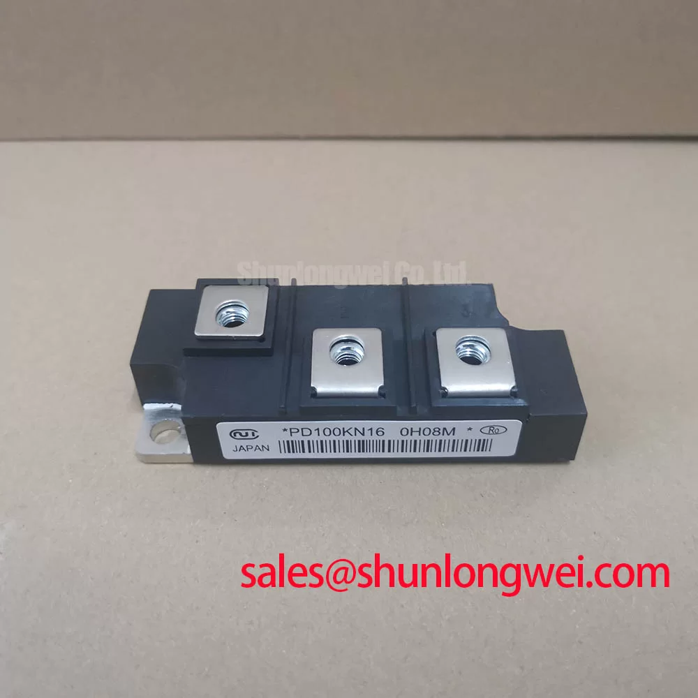
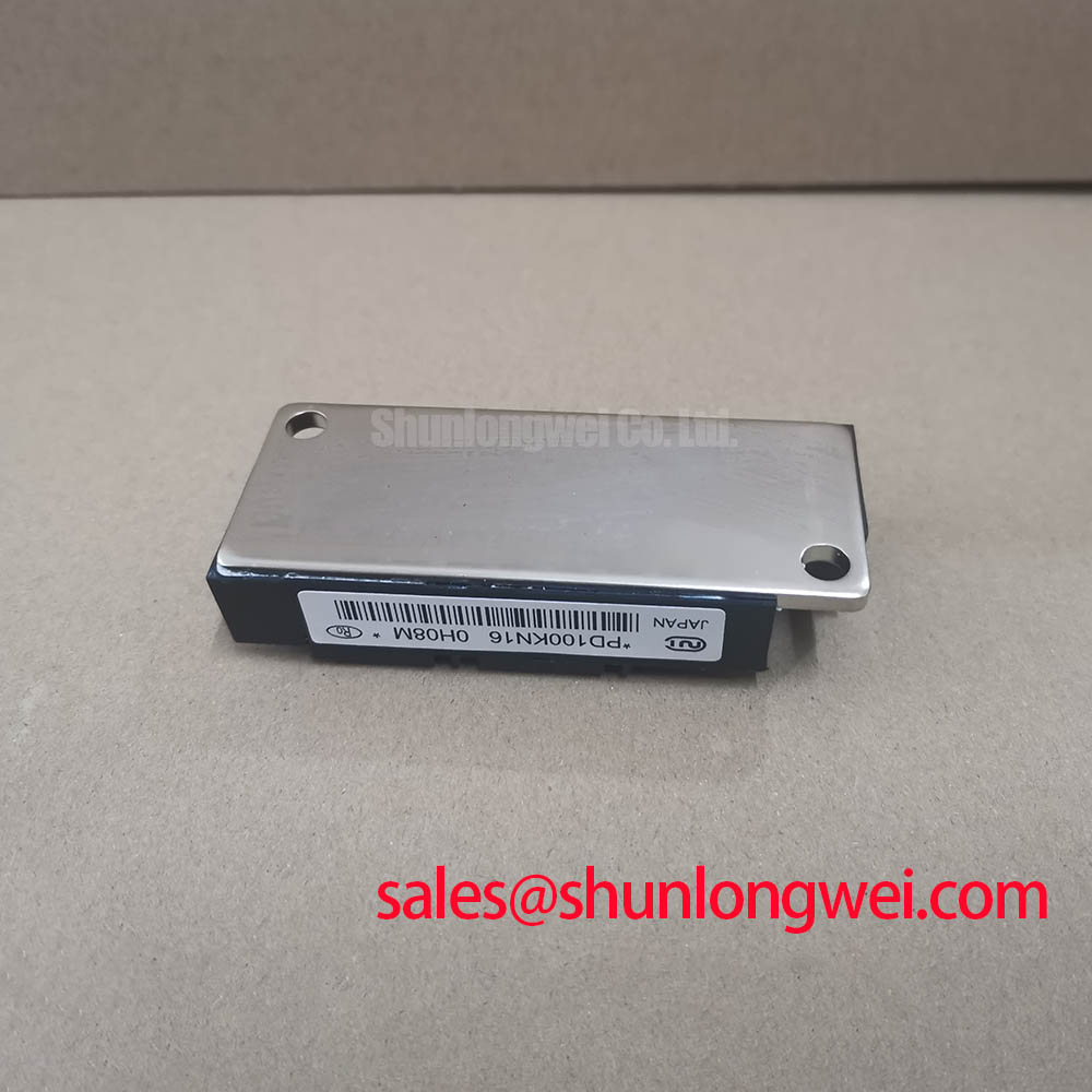
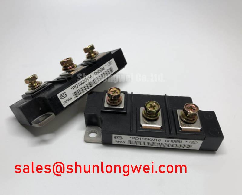
The SanRex (Sansha Electric) device is a Thyristor / Diode Module in an Isolated Power Module housing. Its electrical identity should remain separate from IGBT terminology: reverse-voltage capability is specified as VRRM, not collector-emitter voltage.
Check the main-terminal connections and commutation-loop layout before attributing a switching transient to the module. As a Design Consideration, short, closely coupled outgoing and return conductors can reduce parasitic inductance; the appropriate busbar geometry depends on the rectifier arrangement, clearances, and measured switching behavior.
The product’s primary specification baseline is:
- Manufacturer: SanRex (Sansha Electric)
- Part Number: PD100KN16
- Repetitive Peak Reverse Voltage (VRRM): 1600.0 V
- Average On-State Current (IT(AV)): 100.0 A under the datasheet-specified conditions
- Package: Isolated Power Module
- Configuration / Topology: Thyristor / Diode Module
For commutation assessment, observe reverse-recovery current and the associated terminal-voltage transient together. Peak reverse-recovery current and recovery time describe different aspects of the event; recovery time alone does not establish a soft-recovery characteristic. Use the actual operating current, temperature, and commutation conditions when comparing waveforms, rather than assigning this module an unsupported recovery classification.
Mechanical preparation belongs in the same inspection. Check heatsink contact, seating flatness, terminal alignment, and the specified tightening procedure. Housing isolation does not establish an unrestricted insulation-test voltage: the test connection, duration, and permitted voltage must follow the manufacturer’s procedure. Mounting torque, isolation-test limits, recovery characteristics, surge current ITSM, junction-temperature limits, and semiconductor I²t require the applicable datasheet.
For protective coordination, compare the fuse’s total clearing I²t with the module’s permitted withstand under corresponding conditions. A surge-current rating is not a repetitive operating allowance, and a cooled housing does not establish that the junction has recovered after a fault. The Snubber Loss Balancing Technical Reference provides supporting context for evaluating transient suppression against added dissipation.
Assembly Integrity & Layout Architecture: Implementing Harmonic Current Injection and Line Filter for PD100KN16
Check firing-angle references against the supply phase sequence before interpreting reduced DC output as a defective PD100KN16. As a Design Consideration, delaying thyristor firing changes the rectifier’s conduction intervals and average output; the transfer characteristic depends on bridge topology, load-current continuity, and commutation overlap.
Record input current, DC output, and firing timing together during controlled testing. Phase displacement and current-waveform distortion both affect power factor, so output voltage alone cannot establish reactive-power demand. Any line-filter assessment should use measured harmonic content and the installation’s source impedance rather than a component-level assumption about harmonic compliance.
When evaluating a high-current green hydrogen electrolyzer DC power rectifier, engineers should check the complete bridge arrangement, cooling conditions, and protection coordination. The module’s stated current rating does not establish the assembled rectifier’s continuous output capability.
For replacement screening, PK130FG160 is a separate comparison candidate, not an established drop-in replacement. Use the following checks before approving either part against the equipment drawing.
| Selection check | PD100KN16 | PK130FG160 |
|---|---|---|
| Reverse-voltage rating | 1600.0 V VRRM | Consult datasheet |
| Average on-state current | 100.0 A IT(AV) under the datasheet-specified conditions | Consult datasheet |
| Configuration | Thyristor / Diode Module | Compare circuit diagram |
| Mechanical compatibility | Isolated Power Module | Compare footprint and terminal positions |
| Protection and triggering | Compare gate limits, surge conditions, and fuse coordination before substitution | |
Preventing Spurious Faults: High-di/dt Gate Firing: Pulse-Train Timing Guidelines for PD100KN16
Measure the gate pulse relative to its corresponding cathode at the module connection, not only at the controller output. As an Engineering Recommendation, inspect pulse shape during actual commutation to distinguish trigger-circuit behavior from voltage disturbance in the return path.
💡 Bench Tip: Use ESD-controlled handling and compare cold-state gate-to-cathode readings with a known-good reference before applying powered trigger tests.
A multimeter check can reveal inconsistent junction responses, but it does not establish gate-trigger sensitivity or latching performance. In powered testing, distinguish latching current, needed after triggering, from holding current, below which conduction ceases. Pulse-train timing should support the intended conduction interval without exceeding gate peak or average power limits.
If firing is intermittent, inspect connector continuity, pulse-transformer behavior where fitted, and gate-return routing before changing drive components. Gate-resistor adjustment should follow the measured pulse and manufacturer limits, with confirmation that anode-current rise remains permissible. After a surge event, investigate the protection sequence and thermal recovery conditions before repeating the firing test.