

Content last revised on September 16, 2026
PGH100N8 Thermal Electrical Optimization: RC Snubber Network Optimization for Practical Tuning
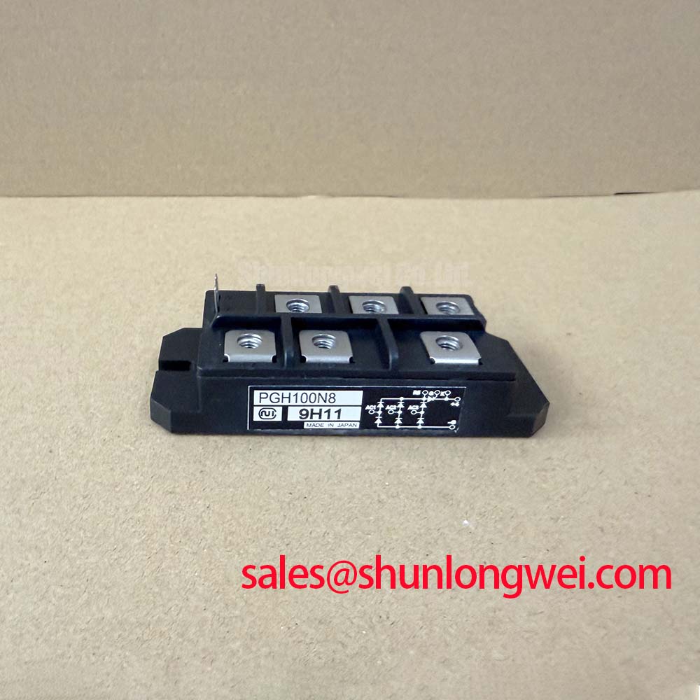
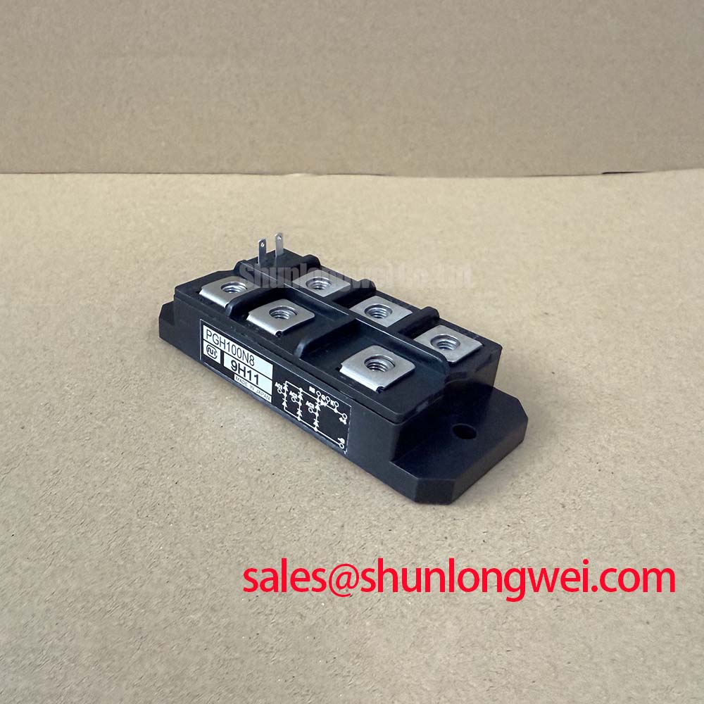
With the unit isolated from the circuit and fully discharged, begin by confirming the terminal identification against the original equipment drawing, then compare the cold diode mode readings across equivalent devices in the same assembly. PGH100N8 is a Nihon Inter, also known as NIEC, thyristor and diode module with an official repetitive reverse voltage rating of 800 V, an average rectified forward current rating of 100 A at Tc 78°C, and a maximum gate trigger current of 100 mA. Its published thermal resistance is 0.30 °C/W per thyristor from junction to case, and the official isolation rating is 2000 V AC for 1 minute.
These figures define the component boundary, not the complete operating limit of an induction heating power supply. A repair engineer should assess the actual heatsink condition, busbar routing, fuse coordination, gate pulse transformer condition, firing board timing, and insulation spacing in the original equipment before returning the converter to service.
| Official Specification | Value and Condition |
|---|---|
| Peak repetitive reverse voltage, VRRM | 800 V |
| Average rectified forward current, IT(AV) | 100 A at Tc 78°C |
| Gate trigger current, IGT | 100 mA maximum |
| Thermal resistance, Rth(j c) | 0.30 °C/W per thyristor |
| Isolation voltage, Visol | 2000 V AC for 1 minute |
The first practical check is the physical path between the PGH100N8 terminals, snubber components, fuse, busbars, and the associated transformer or resonant load. In an induction melting or hardening furnace supply, a long or poorly supported connection can add stray inductance. When current changes rapidly, this inductance can create voltage overshoot across the thyristor path. The relevant repair task is not to copy an arbitrary snubber value from another converter, but to determine whether the original RC network remains electrically intact and appropriately located.
The 800 V VRRM rating is an Official Datasheet Specification. It should be checked against measured repetitive reverse stress at the installed circuit position, including switching transients and mains related conditions. A capacitor with reduced capacitance, a resistor that has changed value, loose snubber wiring, or a cracked solder connection can alter the damping behavior. Inspect the network with power removed, then use an isolated measurement method to compare waveform behavior against the equipment’s documented operating condition during controlled commissioning.
Design Consideration: an RC snubber is intended to limit the rate of voltage rise and damp resonant ringing, while a series saturable reactor may be used in some established converter topologies to shape current rise. Their final values depend on commutation inductance, transformer leakage characteristics, load condition, cable geometry, and firing sequence. The system engineer should verify peak voltage margin against the DC link and measured transient waveform rather than treating the PGH100N8 voltage rating as a target operating voltage.
The module’s published 0.30 °C/W per thyristor junction to case thermal resistance makes case mounting quality important. Before installation, remove hardened compound and inspect the heatsink mating area for burrs, corrosion, and distortion. Apply thermal interface material uniformly according to the equipment maintenance procedure, position the module without forcing its terminals into alignment, and tighten mounting hardware according to the module drawing or the original equipment service documentation.
⚠️ Field Alert: Do not use terminal hardware to pull a misaligned busbar into place, because mechanical stress can compromise both the terminal joint and the insulated module body.
Fuse coordination also needs to be evaluated as a system condition. The available fuse I²t data, prospective fault current, conductor size, and semiconductor protection objective must be compared with the original equipment documentation. No specific fuse I²t value is stated in the available PGH100N8 official data, so a replacement fuse cannot be specified from the module current rating alone. A 100 A average current figure does not define short circuit interruption capability or fault energy withstand.
Where a different NIEC module is being reviewed during repair planning, PGH50N16 can be examined as a related module reference. Electrical ratings, terminal arrangement, thermal interface, control requirements, and equipment schematic compatibility should all be verified before any substitution decision.
PGH100N8 Thermal Electrical Optimization: Gate Trigger Current Dynamics Practical Tuning
Gate circuit verification starts at the module terminals, not at the firing board connector. With the converter safely isolated, trace each gate and cathode return route through the pulse transformer, connector, harness, and protective resistor network. Check for damaged insulation, poor crimp retention, contamination, and unintended shared return paths. A gate pulse that appears adequate at the control board can arrive distorted at the module when the wiring has high impedance or when the pulse transformer is affected by loading.
The PGH100N8 specifies a maximum IGT of 100 mA. This is an Official Datasheet Specification describing the trigger requirement boundary. It does not define a universal firing pulse amplitude, pulse width, repetition method, or gate resistor for every furnace power stage. Those conditions are determined by the original firing circuit, operating frequency, load state, pulse transformer behavior, and required commutation sequence.
Design Consideration: a practical firing assessment observes gate pulse rise behavior, pulse integrity during the intended conduction interval, and repeatability across all installed positions. In circuits using multipulse firing, compare the pulse train at the module connection with the known good channel and confirm that each thyristor receives the intended command at the correct phase relationship. A weak pulse, excessive ringing, or an unstable return reference may contribute to irregular triggering, but each finding should be confirmed through measurement rather than assigned to one cause.
The term back porch is sometimes used by service teams to describe the portion of a gate pulse that maintains useful drive after the initial edge. Whether that feature is present depends on the original trigger board. It should not be added or modified without evaluating the gate circuit and the manufacturer documentation for the complete equipment. Repeated gate stress can also arise from an external firing circuit fault, so maintenance should include the pulse transformer insulation, connector condition, and control board output stage.
💡 Bench Tip: Keep gate leads protected from electrostatic discharge and record cold comparison readings before energizing the replacement module, because a matched baseline is more useful than a single isolated measurement.
In bridge sections where command overlap is possible, firing delay and nonoverlap behavior need to be reviewed at the system level. The general concept of dead time in switching bridge control is useful when examining external command timing, although the correct timing relationships for a thyristor converter remain dependent on its commutation method and original controller design. The PGH100N8 data provided here does not publish a prescribed delay angle or firing sequence.
PGH100N8 Circuit Protection & Reliability: Calibrating Dynamic Firing Delay Angle Adjustment
A controlled rectifier changes its delivered DC voltage as its firing angle changes relative to the AC waveform. In practical service work, this relationship is visible as a change in DC bus level, input current waveform, transformer loading, and available heating power. At lower delay angles, the converter can transfer more of the available AC waveform into the load. At larger delay angles, delivered power reduces and reactive demand may become more significant. The actual response also depends on supply impedance, commutation overlap, load characteristics, and the furnace control strategy.
For a medium frequency induction melting or hardening furnace, treat firing angle calibration as an equipment level procedure. Verify phase reference quality, firing board synchronization, pulse transformer polarity, and the intended feedback loop before changing adjustment settings. A phase reference that is noisy or shifted can produce an unexpected firing position. A misrouted gate return or inconsistent firing transformer channel can create a similar operational symptom. Oscilloscope comparison against a documented known good signal path is preferable to adjusting delay settings based only on output current.
The 100 A at Tc 78°C rating should be read in its stated condition. Case temperature is part of the rating condition, so it cannot be separated from heatsink performance, airflow, coolant condition where applicable, thermal interface quality, and duty cycle. During commissioning, monitor temperatures by the approved equipment method and verify that the thermal path is consistent across parallel or bridge positions. Uneven case heating may indicate a mounting, cooling, current sharing, or control issue that requires further diagnosis.
Some converter assemblies use complementary rectifier or freewheel stages around the main controlled section. For topology review, the PK55FG120 is a related power module reference that can be considered when tracing adjacent power paths. Its presence in an equipment bill of materials would not establish electrical interchangeability with PGH100N8; terminal functions, voltage ratings, current ratings, and circuit role must be confirmed from the schematic.
Design Consideration: keep high voltage terminal creepage and clearance paths clean, dry, and free of conductive dust or loose hardware. The official 2000 V AC for 1 minute isolation specification applies to the defined module isolation test condition. It does not replace the insulation coordination requirements of the assembled cabinet, busbar system, harnesses, enclosure, and maintenance procedure.
Where the firing board includes insulated gate drive elements, technicians should avoid unsupported conclusions about long term dielectric condition. Time dependent dielectric breakdown describes a general dielectric degradation mechanism, but no lifetime figure or gate oxide reliability claim is asserted here for PGH100N8. Use approved insulation tests and the original equipment acceptance criteria.
PGH100N8 Operational Boundaries: Evaluating Sinusoidal 10ms Half Cycle Surge Current Limits
Before testing overload recovery, separate the published parameters from unpublished ones. The provided PGH100N8 official data identifies 800 V VRRM, 100 A IT(AV) at Tc 78°C, 100 mA maximum IGT, 0.30 °C/W per thyristor, and 2000 V AC for 1 minute isolation. It does not provide a sinusoidal 10 ms half cycle surge current rating, ITSM, in the supplied specification set. A numerical surge limit must therefore not be inferred from the average current rating.
When investigating a suspected line disturbance, failed commutation event, or load fault, inspect the semiconductor fuse condition, busbar joints, snubber network, cooling path, and firing timing before applying reverse voltage again. A module can show apparently reasonable static diode mode behavior while an external circuit fault remains active. Conversely, an unusual cold reading can result from a parallel circuit path if testing is performed in assembly. Isolate the relevant connections when the service procedure permits and compare readings with the circuit drawing.
Design Consideration: a surge event is evaluated by considering its current waveform, duration, initial junction temperature, repetition, protection response, and the interval before reverse voltage is reapplied. The system engineer should use the manufacturer’s complete surge data and the equipment fault study where available. The published thermal resistance helps assess normal thermal transfer from junction to case, but it does not create a valid surge current rating by calculation alone.
For gate drive and protection checks under demanding commutation conditions, the practical notes in Evolution of Negative Off Bias Gate Drive Circuits can assist with reviewing external drive architecture. PGH100N8 is a thyristor and diode module, so any gate drive modification must remain specific to the original thyristor firing topology and be validated in the complete system.