




Content last revised on September 19, 2026
PHT40016 Circuit Protection & Reliability: Calibrating Semiconductor Protection Fuse Selection
Before selecting a semiconductor fuse, obtain the PHT40016 manufacturer data for its allowable short-circuit withstand, surge-current capability, I²t limit, and recommended protection arrangement. The supplied product information confirms the 1600.0 V voltage class and 400.0 A current class, but it does not provide a fuse coordination table or a verified I²t value. Those values must not be inferred from the continuous current label.
In a dead-short event, the fuse must clear the fault before the energy delivered to the thyristor or diode exceeds the semiconductor’s permitted withstand. The practical review compares the fuse clearing I²t, total clearing time, prospective fault current, source impedance, transformer leakage, and the module’s official fault limits under the stated test conditions. A fuse with an apparently suitable current label can still be unsuitable if its clearing energy or voltage interruption behavior does not coordinate with the bridge.
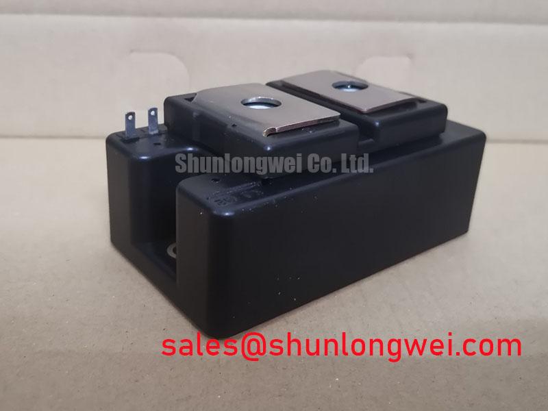
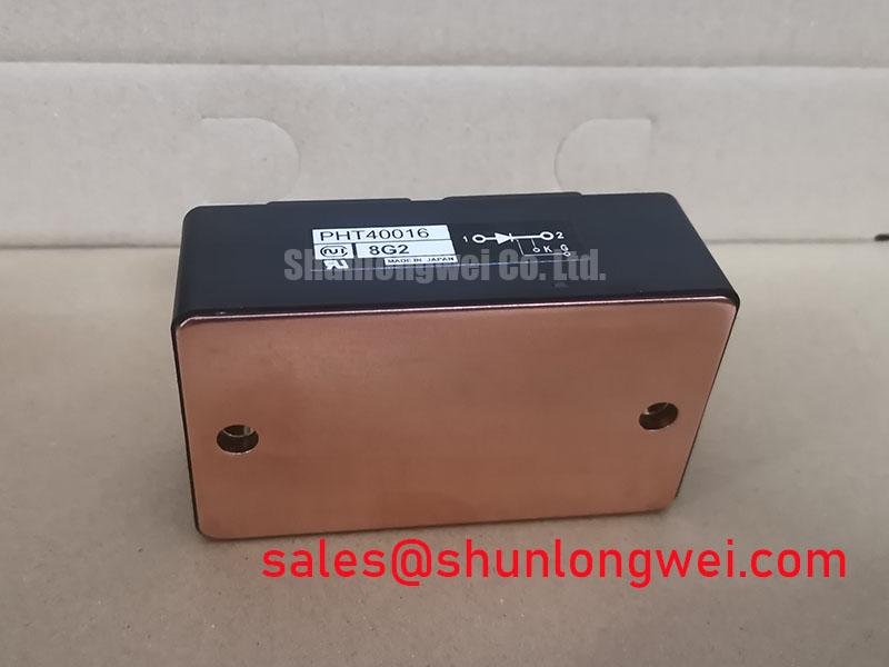
Inspect each fuse connection for heat discoloration, looseness, and uneven contact pressure. Check that the fuse voltage rating is compatible with the rectifier’s actual fault interruption duty and that the assembly provides the required creepage and clearance. The PHT40016 terminal layout, polarity, and any gate or auxiliary terminals must be confirmed from the original drawing rather than assumed from another NIEC module.
When the rectifier uses a controlled thyristor bridge, the trigger circuit also needs review after a fuse event. Verify the gate-cathode wiring, pulse isolation, trigger return path, and the controller’s inhibit timing. IGT and VGT are official device-specific parameters that must come from the relevant PHT40016 datasheet; they should not be substituted with generic thyristor values.
Field Alert: Disconnect the DC link and verify the absence of stored energy before removing fuses, gate leads, or busbar connections.
Assembly Integrity & Layout Architecture: Implementing Mechanical Mounting Torque Sequence and Thermal Management for PHT40016
The isolated power module depends on a mechanically sound thermal interface, but the official PHT40016 mounting torque, baseplate flatness requirement, terminal torque, and thermal resistance Rth(j-c) were not supplied in the product record. Obtain those values from the applicable NIEC drawing before tightening hardware. A generic torque value can distort the module, reduce contact uniformity, or damage a threaded insert.
Clean the heatsink contact area and check it for burrs, contamination, and visible high spots. The heatsink should present a stable, even surface so that the module baseplate is supported across its intended contact region. Apply thermal interface material as a uniform thin layer according to the approved assembly process. Excess compound can migrate toward insulation surfaces and does not compensate for a warped heatsink.
Tighten the mounting fasteners in the sequence specified by the manufacturer, using a calibrated tool and a controlled cross-pattern when the mechanical drawing requires it. Record the applied torque and inspect the module after installation for case movement, tilted hardware, or stress around the mounting points. Terminal connections should be supported by the busbar or cable geometry so that tightening force is not transferred into the module body.
Busbar architecture deserves the same attention as the mechanical stack. Keep the high-current forward and return paths compact and closely coupled to reduce stray inductance. During turn-off, parasitic inductance can create voltage overshoot when current changes rapidly. The system designer should verify the peak voltage with an oscilloscope during switching or commutation tests and compare it with the official device voltage boundary, including the actual DC-link operating condition.
If the driver or interface drawing provides a separate auxiliary emitter or trigger return, route that connection independently from the high-current emitter or cathode path where the circuit requires it. Do not assume that the PHT40016 includes a Kelvin terminal unless the manufacturer’s terminal diagram confirms it. Gate-loop inductance can contribute to ringing and false triggering, so the gate path, return path, isolation barrier, and damping network should be assessed as one complete loop.
For current feedback, the controller may use a Hall, GMR, or TMR sensing stage depending on the equipment design. Background information on industrial magnetic current sensing is available from Giant Magnetoresistance and TMR Sensors for Industrial Current Measurement. That reference does not define the PHT40016 electrical limits; it is relevant only when checking the measurement chain used to regulate or protect the rectifier.
Transient Dynamics & Electrical Design: Sinusoidal 10 ms Half-Cycle Surge Current on PHT40016
A service engineer should not approve a half-cycle overload from the 400.0 A rating alone. The PHT40016 surge-current capability, ITSM, test waveform, initial junction temperature, and permitted recovery condition must be taken from the official datasheet. The supplied information does not provide a verified ITSM value, so a numerical surge limit cannot be stated responsibly.
For a sinusoidal half-cycle event, capture the current waveform at the module terminal and identify the actual peak, duration, repetition pattern, and starting temperature. Then compare the event with the manufacturer’s test conditions. A single short pulse and repetitive commutation stress are different service conditions, even when their peak current appears similar. Transformer inrush, DC-link charging, regenerative energy, and an uncontrolled bridge fault can also produce different thermal and electrical stress profiles.
Reverse voltage reapplication requires particular care in a thyristor or diode bridge. Confirm that the conducting path has fully recovered before the opposite voltage is applied, and verify the firing sequence against the line phase relationship. Unexpected gate pulses, noisy trigger returns, or a bootstrap driver with insufficient high-frequency capacitor charge can alter the intended commutation sequence. The capacitor value, diode recovery behavior, and driver supply margin are system design matters and must be validated on the actual control board.
Where a pulse train is used, verify that the trigger amplitude, pulse width, repetition, isolation, and gate-cathode return remain within the PHT40016 datasheet limits. Do not assign generic IGT or VGT values to this model. The correct bench procedure is to observe the gate and power waveforms together, then compare the measured trigger conditions with the manufacturer’s specified limits under the operating temperature and load being tested.
An electrolyzer rectifier may also contain an industrial display or HMI used for current, voltage, and alarm status. Display selection and optical behavior belong to the control-panel subsystem; the Truly Semiconductors industrial display modules reference should not be treated as evidence of any PHT40016 display or interface feature.
PHT40016 Circuit Protection & Reliability: Mitigating DC Ripple Currents in High-Efficiency Electrolyzer Rectifiers
For kiloampere-level DC output, a six-pulse or twelve-pulse rectifier must be evaluated as a complete power topology. The PHT40016 may be considered for the semiconductor positions only after the bridge polarity, device ratings, trigger method, cooling arrangement, and current-sharing behavior have been verified from the original equipment drawings. The official model data supplied here establishes 1600.0 V, 400.0 A, and an Isolated Power Module package description; it does not establish a particular six-pulse or twelve-pulse circuit.
A six-pulse bridge is generally simpler to inspect, but its DC output ripple and line-current pattern must be checked against the electrolyzer power supply requirements. A twelve-pulse arrangement can use phase-shifted transformer secondaries and an interphase transformer to combine bridge outputs. The IPT must be evaluated for insulation, saturation, leakage, thermal loading, and current sharing under the real DC load. Its performance cannot be guaranteed by matching the module current label alone.
During commissioning, measure the current in each parallel path and inspect the busbar symmetry. Unequal path resistance, unequal inductance, timing variation, or thermal imbalance may cause one bridge leg to carry more current than expected. Use synchronized voltage and current measurements to examine commutation overlap, turn-off overshoot, gate ringing, and DC ripple. The system engineer should determine acceptable margins from the equipment specification and verify them under startup, steady load, fault clearing, and controlled shutdown.
The front-end protection stage should be reviewed with the rectifier topology. The SSIL2890S46C can be evaluated as a neutral complementary-stage reference when reviewing upstream rectification or associated circuitry, but it is not an automatic substitute for the PHT40016. Any cross-model comparison must confirm voltage class, current path, terminal arrangement, thermal interface, triggering method, and mechanical fit.
For a different device family, engineers may also review PGH50N16 as a neutral cross-reference point during system evaluation. It should not be treated as a direct replacement without electrical, mechanical, thermal, and control verification. Long-duration testing should monitor junction-related thermal behavior, busbar temperature, fuse condition, trigger stability, and ripple current rather than relying on a single surface temperature reading.
Additional power-conversion background can be reviewed in The 1200 V CoolSiC MOSFET Advantage in Three. That article concerns a different semiconductor technology and voltage class; it does not provide PHT40016 ratings or certify the performance of a thyristor or diode bridge.