

Content last revised on September 10, 2026
Panel Bezel Integration and Perimeter Gasket Shock Isolation
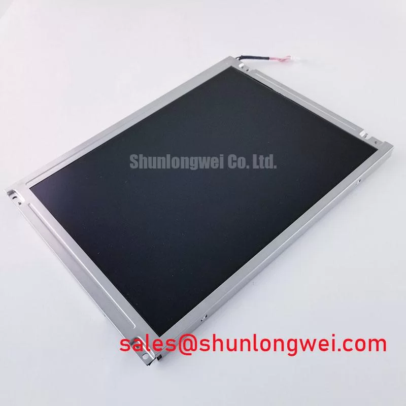
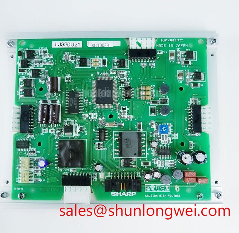
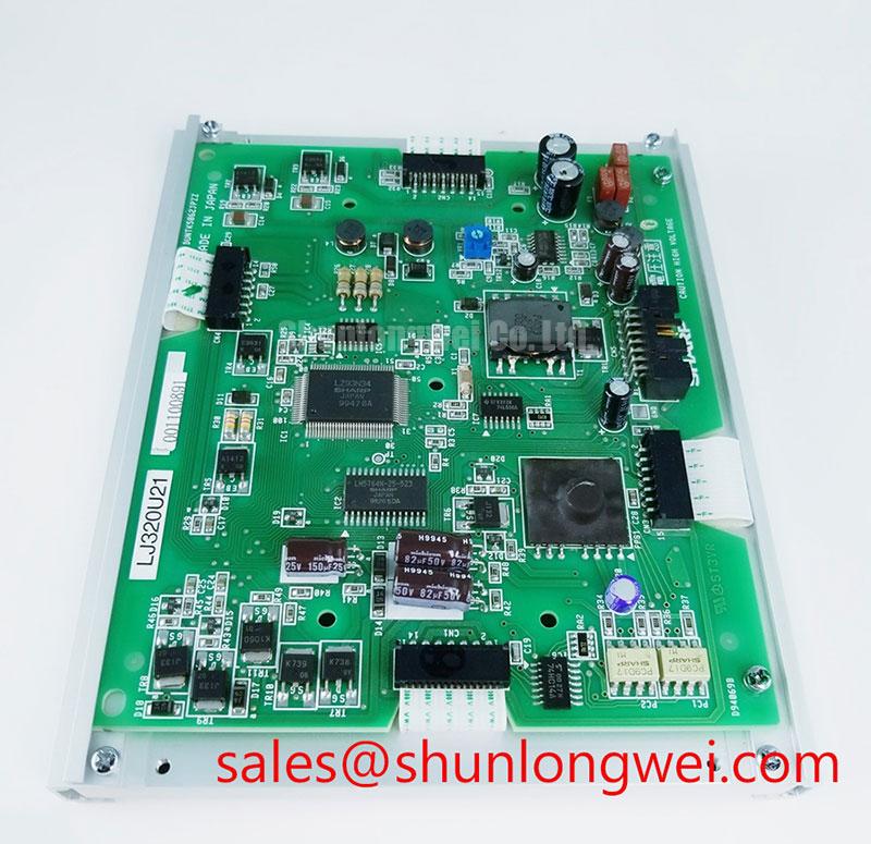
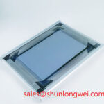
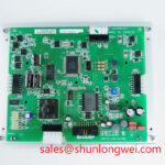
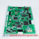
With the equipment isolated from power, begin by checking the installed panel label, connector seating, bezel pressure marks, and the display opening before removing the LJ320U21. This Sharp unit is identified as an Industrial Grade LCD/HMI Panel in a TFT LCD Display Module format. The available product data does not define its outer dimensions, active area, mounting locations, connector pinout, supply rails, interface standard, backlight arrangement, or optical ratings. Those items must be matched against the original panel documentation and the host equipment drawing before installation.
Bezel integration deserves particular attention when a panel appears normal on the bench but develops uneven brightness, shadowing, or pressure related image artifacts after final assembly. Design Consideration: the enclosure should support the module only at approved mechanical points and should not impose uncontrolled compression through a decorative front frame, gasket, cable clamp, or rear retention plate. Engineers should inspect whether the equipment bezel remains flat when fasteners are tightened and whether a perimeter seal transfers force into the chassis rather than into the visible display area.
The requested assembly information does not provide an official fastener size, tightening torque, cross pattern requirement, or gasket compression specification for the LJ320U21. A system integrator should therefore use the original equipment mechanical documentation rather than applying generic torque values. If a panel shows a dark patch only after the enclosure is closed, loosen the retention structure, inspect the panel seating condition, and compare the image with the display operating outside the bezel. That process helps separate mechanical stress from a signal or backlight issue.
Signal routing must also be verified from the original documentation. Differential pair impedance, pair skew, cable shielding, and interface termination cannot be assigned to this model without the official interface specification. Design Consideration: keep the original signal path geometry intact where possible, particularly where the cable passes near contactors, motor leads, or switching power equipment. During a repair evaluation, compare connector orientation, keying, contact count, and cable exit direction with the removed unit before treating another display as mechanically compatible.
⚠️ Field Alert: Disconnect system power and allow stored energy to discharge before inserting or removing the display cable, because live connector handling can stress signal and supply pins.
Viewing Direction, Grayscale Appearance, and Optical Integration Assessment
The available official information identifies the LJ320U21 as a Sharp TFT LCD module but does not confirm its LCD mode, viewing direction, contrast ratio, anti glare surface treatment, luminance, color characteristics, or backlight technology. It should not be described as a TN, IPS, MVA, LED backlit, or sunlight readable panel unless those attributes are verified on the original factory documentation for the installed display.
In field work, an image that looks acceptable from one position but washes out, shifts tone, or loses grayscale separation from another angle should be assessed as an optical integration observation rather than attributed to a specific panel technology. Check the viewing position from the actual operator location, compare it with a known working installation when available, and inspect the front window for contamination, abrasion, internal reflections, or pressure against the polarizer surface. Ambient illumination can make a marginal display appear weak even when the data path is stable.
For equipment telematics displays, technicians should separate three observations: whether the panel receives a valid image, whether the image remains stable across the intended viewing direction, and whether the protective window or enclosure lighting conditions reduce legibility. A bright workshop lamp or direct outdoor light can reveal reflections that are not present during bench testing. Design Consideration: evaluate the panel together with the final bezel, front window, and intended operator sight line rather than judging it only while unsupported on a service bench.
Backlight aging, if present in the host assembly, cannot be assigned a lifetime value from the available LJ320U21 factory data. No L fifty, L seventy, B fifty, or operating hour claim should be inferred for this model. If the image is visible under a strong external light but appears dark during normal operation, verify the panel supply, the original backlight drive path, brightness control signal, and any interlock conditions specified by the equipment manufacturer. For broader panel selection and optical evaluation practices, consult Sharp Display Solutions alongside the documentation for the exact installed assembly.
Industrial EMI Noise Assessment, Chassis Shielding Continuity and Common Mode Ferrite Chokes
A display that develops moving horizontal bands, intermittent pixel disturbance, or image loss near high power machinery should be checked at the cable and chassis interfaces before the panel itself is judged responsible. The official data supplied for the LJ320U21 does not state EMC compliance, shield termination method, cable type, interface standard, or immunity level. Any claim that the module independently meets an equipment level EMC standard would be unsupported.
Design Consideration: inspect the continuity of the host chassis bonding arrangement, the condition of cable shields, connector latches, and routing separation from noisy power conductors. A damaged or partially unseated display cable can create symptoms that resemble electrical interference. Where the equipment design uses common mode suppression components, retain the original arrangement and verify that replacement cable routing does not defeat the intended shield termination. Oscilloscope checks should be compared against a known good signal path when practical, with the final judgment made by the system engineer.
Variable frequency motor systems, switching supplies, and high voltage assemblies can introduce conducted or radiated disturbances into a display subsystem. The LCD module should not be associated with semiconductor avalanche behavior, but engineers investigating an upstream power fault can review the general physical mechanism described in Avalanche Breakdown in High Voltage Power Semiconductors. That reference does not establish any rating or failure mechanism for the LJ320U21; it simply helps distinguish power stage investigation from display interface troubleshooting.
When compatibility assessment requires an alternate panel, verify the original mechanical envelope, image format, interface, power sequence, and host firmware expectations first. The LM057QC1T08 can be reviewed as a separate display module for documented comparison, but it should not be assumed to be a direct replacement for the LJ320U21 without a complete equipment level check. For a practical reference covering TFT LCD selection and common integration checks, see The Ultimate Guide to Industrial TFT LCD Technology.
Luminance Output and Backlight Reliability Verification
If the LJ320U21 produces a stable image at first and then becomes dim, intermittent, or blank after the equipment warms up, test the display subsystem as a chain. Confirm the panel connector lock, inspect the harness for strain and contact wear, verify that the host supplies appear at the display connector according to the original documentation, and check whether the symptom changes with the equipment brightness setting. The system integrator should verify the required supply voltage and power sequencing from the original panel documentation because these values are not included in the available factory data.
Do not assume that every dark screen is a failed LCD. A visible faint image under external illumination may direct attention toward the illumination path, while a completely absent or unstable image can require investigation of the host controller, cable, power rail, or display interface. These observations are diagnostic starting points rather than proof of a single cause. Where the assembly uses a separate illumination or display stage, the LQ150X1LG11 may be reviewed as another display product during system level evaluation, subject to its own documentation and compatibility checks.
Design Consideration: heat from adjacent electronics, poor chassis contact, enclosure contamination, and restricted airflow can affect the overall display assembly. The available Sharp information does not specify permissible thermal interface materials, heat spreader geometry, PWM dimming frequency, duty cycle behavior, acoustic performance, or brightness decay characteristics for the LJ320U21. Retain the original thermal arrangement where possible, avoid trapping the display cable under mounting hardware, and validate screen stability after the enclosure has reached its normal operating condition.
For potential use in heavy earthmoving equipment telematics displays, technicians should treat vibration resistance, enclosure sealing, cable retention, and operator visibility as equipment level verification tasks. The panel identification, TFT LCD module format, and original system documentation form the reliable basis for repair decisions.